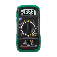
Alternative voltage measurement
Place the red probe into the “V.. mA” jack and the
black probe into the “COM” jack.
Turn the switch to V~ and connect the probe to the
power supply or load to be measured.
Note: Refer to point 1, 2, 3 and 4 for direct current
voltage measurement.
Place the back probe into the “COM” jack and red one
into the “V/ / HZ” jack.
Turn the switch to the “COM” jack, and connect the
probe to the resistor being measured and read the
result on the display.
Insert the black lead to the “COM” jack the red one into
the “V..mA” jack.
Connect the red test lead to “V..mA” jack and the
black Turn the switch to the range, and connect
the red probe to the positive pole of the diode being
measured and the black one to the negative pole, read
the approximate forward voltage drop of the diode on
the display.
Notice
1. If the resistor being measured is greater than the maximum
value of the selected range, the display will show “1”,
requiring the selection of a higher range. It normally takes a
few seconds for the reading to get stable when measuring a
resistor larger than 1M.
2. In default of input, for instance, open circuit, the display
shows “1”.
3. When measuring an online resistor, de-energized the
circuit being measured and discharged capacitors.

 Loading...