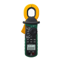
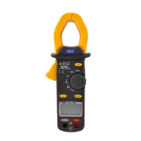
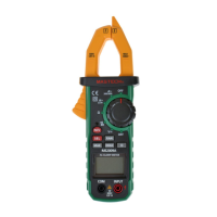
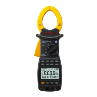
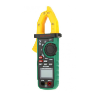
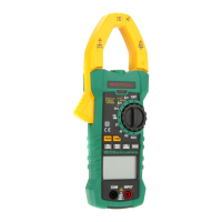
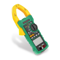
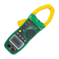
Digital Clamp Meter
The Digital Clamp Meter is a portable, professional measuring instrument designed for a wide range of electrical measurements. It features an LCD display with backlight for easy reading, even in low-light conditions. The device is equipped with a measuring range switch that can be operated with a single hand, enhancing user convenience. It also incorporates overload protection and a low battery indicator to ensure safe and reliable operation. This multifunction meter is suitable for professionals, factories, schools, hobbyists, and general household use.
Function Description
The meter is capable of measuring various electrical parameters, including:
- AC Current: Measures alternating current flowing through a conductor without breaking the circuit, using the clamp head.
- DC Current: Measures direct current.
- AC Voltage: Measures alternating voltage.
- DC Voltage: Measures direct voltage.
- Frequency: Measures the frequency of AC voltage and current signals.
- Duty Ratio: Measures the duty cycle of AC voltage and current signals.
- Resistance: Measures electrical resistance.
- Capacitance: Measures electrical capacitance.
- Circuit Continuity: Tests for continuity in a circuit, often with an audible buzzer.
- Diode Test: Tests the functionality of diodes.
- Non-Contact Voltage (NCV) Detection: Detects the presence of AC voltage without direct contact, enhancing safety.
The meter offers both automatic and manual measuring range modes. It includes a reading hold function to freeze the displayed value for convenient recording. Additionally, it features maximum and minimum measurement functions, allowing users to capture the highest and lowest values during a measurement session. The clamp head also supports frequency measurement. For enhanced efficiency, the meter has an auto power-off function and a relative measuring function, which allows for measurements relative to a stored reference value.
Usage Features
To ensure safe and accurate operation, users should always adhere to standard safety procedures and the guidelines provided in the operation manual.
Preliminary Steps:
Before use, always check the meter for any damage incurred during transportation or storage. Ensure the probe is in good condition, with no damaged insulation or bare metal wire. Use only the provided probe or an identical one with the same performance level.
General Usage:
- Always select the correct function and measuring range for the task at hand.
- Avoid exceeding the stated indication value for each measuring range.
- When measuring a live circuit, do not touch the metal part of the probe tip.
- For voltages exceeding 60 V DC or 30 V AC (RMS), keep fingers behind the finger protection device.
- Do not measure voltages greater than AC 750V.
- In manual measuring range mode, when measuring an unknown value, start with the highest range.
- Before changing the measuring function, remove the probe from the circuit.
- Never measure resistance, capacitance, or diodes in a powered circuit.
- Avoid connecting the meter to a voltage source when testing currents, resistors, capacitors, diodes, or circuit connections.
- Discharge capacitors completely before measuring capacitance.
- Do not use the meter in explosive, vaporous, or dusty environments.
- Discontinue use immediately if any abnormal phenomena or failure is observed.
- Ensure the meter's bottom case and battery cover are securely fastened before use.
- Avoid storing or using the meter in direct sunlight, high temperatures, or high humidity.
Specific Measurement Modes:
- Reading Hold: Press the "HOLD/B.L" button to freeze the current reading on the display. Press it again to release.
- Measuring Range Switch: The "RANGE" button switches between automatic and manual measuring range modes. In manual mode, each press cycles through ranges. Holding the button for more than 2 seconds returns to auto-ranging.
- Frequency/Duty Ratio Switch: In AC voltage or current mode, press "Hz/%" to measure frequency. Press it again to measure duty cycle. Another press reverts to voltage/current measurement. This function is not available in maximum/minimum value measurement mode.
- Maximum/Minimum Measurement: Press "MAX/MIN" to enter MAX mode, which displays the maximum value. Press again for MIN mode (minimum value). A third press shows the difference between MAX and MIN. Holding the button for more than 2 seconds restores normal measuring range. This mode operates in manual ranging.
- Function Switch (FUNC): In resistance mode, "FUNC" cycles between resistance, diode test, and continuity detection. In voltage and current modes, it switches between AC and DC measurements.
- Relative Measurement (REL/INRUSH): Tapping this button enters relative measurement mode, storing the current display value as a reference. Subsequent readings show the difference from this reference. This function is only available in manual mode.
- Backlight and Clamp Head Light: Press "B.L/HOLD" to activate the backlight, which turns off automatically after about 30 seconds. Holding it for more than 2 seconds turns off the backlight immediately. In current mode, the clamp head light also turns on. Excessive use of the backlight can shorten battery life.
- Automatic Power-Off: The meter automatically powers off after 15 minutes of inactivity to save battery. A buzzer will sound five times one minute before shutdown. Pressing "FUNC" turns it back on. Holding "FUNC" during power-on disables this feature.
- Current Measurement: Set the switch to 'A'. Open the clamp head with the trigger and clip it around a single conductor of the circuit. Read the current value. Ensure only one lead is clamped for accurate results, and position the lead at the center of the clamp. Maximum input AC current is 1000A.
- Voltage Measurement: Insert probes into COM (black) and INPUT (red) jacks. Set the switch to 'V' or 'mV'. Press "FUNC" to switch between DC and AC voltage. Connect probes in parallel with the voltage source or load. The meter will alarm if readings exceed 750V rms AC.
- Resistance Test: Insert probes into COM (black) and INPUT (red) jacks. Set the switch to 'Ω'. Connect probes to the resistor or circuit. Ensure the power supply is disconnected and capacitors are discharged before testing circuit impedance.
- Diode Test: Insert probes into COM (black) and INPUT (red) jacks. Set the switch to 'Ω' and press "FUNC" to select diode test. Connect the red probe to the diode anode and the black probe to the cathode.
- Circuit Continuity Test: Insert probes into COM (black) and INPUT (red) jacks. Set the switch to 'Ω' and press "FUNC" to select continuity test. Connect probes to the circuit. An audible buzzer indicates continuity (resistance less than 50Ω). Ensure the power supply is disconnected and capacitors are discharged.
- Capacitance Measurement: Insert probes into COM (black) and INPUT (red) jacks. Set the switch to 'nF'. After completely discharging the capacitor, connect probes to its ends.
- NCV Measurement: Turn the meter to NCV mode. Place the top of the meter near a conductor. If the test voltage is greater than 110 Vac (RMS), the indicator will light up, and the buzzer will sound. Note that voltage may still exist even without an indication, and external interference can trigger false alarms.
Maintenance Features
Proper maintenance ensures the longevity and accuracy of the Digital Clamp Meter.
- Cleaning: Clean the meter with a damp cloth and mild detergent. Avoid using abrasives or solvents.
- Power Off: Always switch the measuring range to the OFF position when the meter is not in use.
- Battery Removal: If the meter will not be used for an extended period, remove the battery to prevent damage from leakage.
- Battery Replacement: When the low battery symbol ("") appears on the LCD, replace the battery immediately. To do this, unscrew the fastening screw of the battery cover, remove the cover, replace the 9V 6F22 battery, and then reattach the cover. Ensure correct battery polarity.
- Probe Replacement: If the probe is damaged (e.g., bare metal wire), replace it with another identical probe or one with the same level of performance (1000V, 10A).
- Internal Adjustments/Repairs: Do not attempt to open the meter's bottom case for adjustments or repairs unless you are a qualified technician with a full understanding of the meter and electrical shock hazards.
- Safety Precaution: Before opening the meter's bottom case or battery cover, always remove the probe from the circuit to be measured to prevent electric shock.