All common input ends to be measured are
connected with common output socket of
black test probe or dedicated multifunction
test socket.
Input Socket
Description
Positive input end of 10A
(connected with the red test probe).
10A
VΩHz
TEMP
07 08
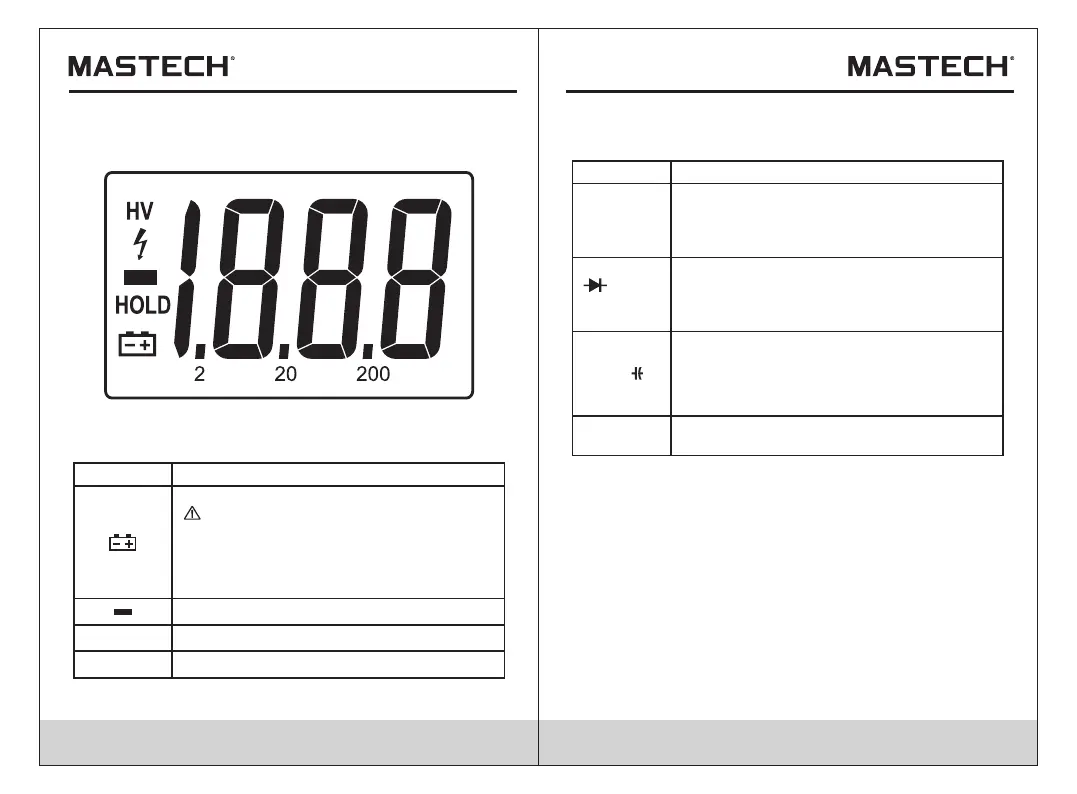
Table 1 Display Symbols
Low battery.
To avoid wrong readings causing
electric shock or personal injury,
when the low battery symbol appears,
the battery should be replaced
immediately.
Symbols
Indication
Negative input polarity indication
Keep the current measurement value
HOLD
Table 2 Input Socket
COM
mA,
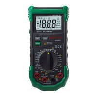
2.2 LCD display
See Table 1 for information about the display.
Fig. 1 Display
HV
High voltage symbol, in AC600V or DC600V.
Positive input end of voltage, resistance,
frequency, diode, buzzer measurement and
temperature test (connected with the red test
probe).
Positive input end of current mA, temperature
and triode hFE (connected with output socket
of black test probe or dedicated multifunction
test socket).
2.3 Input socket