3/20 Rev. A 57-02699
10
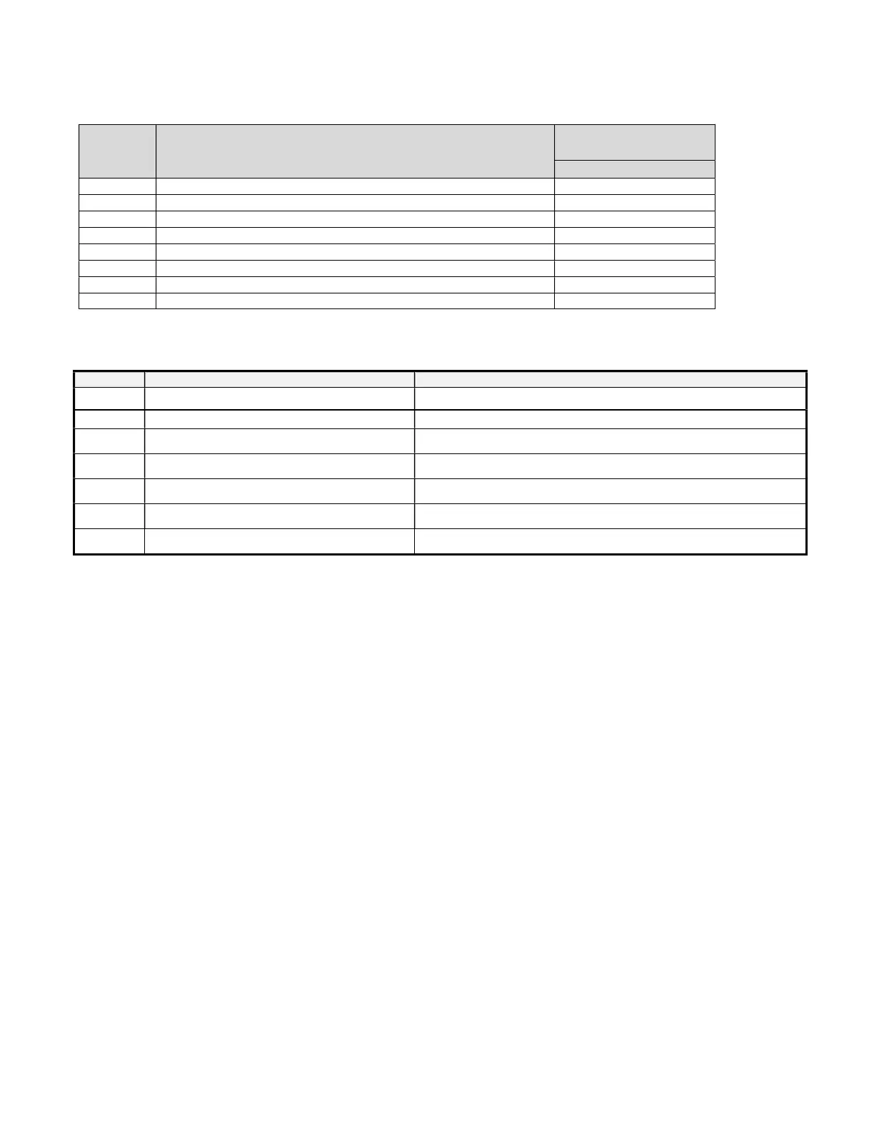
Here is a list of the parameters the value of which can be changed in the programming mode, as well as their ranges.
Display
Symbol
Description
Factory’s
Setting
SEt Temperature set point
Hy Cut-out temperature is Set + Hy, Differential
LS Minimum Temperature Set Point
Us Maximum Temperature Set Point
ALU High Temperature Alarm
ALL Low Temperatyre Alarm
Us High temperature alarm is enabled after a delay
Temperature Alarm Delay
ALARM SIGNALS
“P1” Room probe failure Compressor output according to par. “Con” and “COF”
“HA” Maximum temperature alarm Outputs unchanged.
“LA” Minimum temperature alarm Outputs unchanged.
“dA” Door open Compressor and fans restarts
“EA” External Alarm Output unchanged
“CA” Serious External alarm(i1F=bAL) All output off
“CA” Pressure switch alarm (i1F=PAL) Outputs unchanged.
NOTE:
Probe alarm “P1” starts some seconds after the fault in the related probe; they automatically stop some seconds after the
probe restarts normal operation. Check connections before replacing the probe.
Temperature alarms “HA” and “LA” automatically stop as soon as the thermostat temperature returns to normal values
and when defrost starts.
ELECTRICAL CONNECTIONS
The controller is provided with screw terminal block or male terminals to connect cables with a cross section up to 2,5 mm
2
. Before
connecting cables make sure the power supply complies with the control’s requirements. Separate the probe cables from the
power supply cables, from the outputs and the power connections. Do not exceed the maximum current allowed on each relay, in
case of heavier loads use a suitable external relay.
FINAL CHECK LIST
A. Check operating pressures.
B. Check electrical requirements of unit to supply voltage.
C. Set temperature control for desired temperature setting.
D. Check to make sure the compressor switch, behind the front grill, is on before start up the cabinet.
E. Check condensing unit for vibrating or rubbing tubing. Dampen and clamp as required.