13
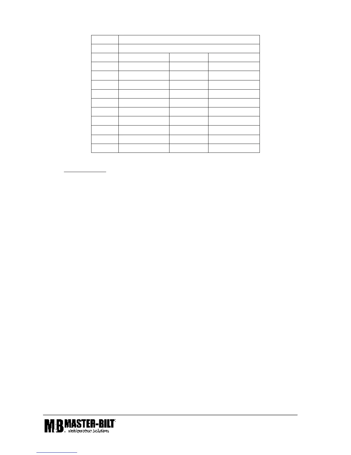
Table 5
Lbs. of R-449A to fill Liquid line by Length
Length
Liquid Line Size (in.ODS)
Feet 3/8" 1/2" 5/8"
5 0.18 0.34 0.54
10 0.36 0.67 1.08
15 0.54 1.00 1.62
20 0.72 1.34 2.16
25 0.9 1.67 2.7
30 1.08 2.00 3.24
50 1.8 3.35 5.4
75 2.7 5.01 8.1
100 3.6 6.7 10.8
150 5.4 10.1 16.2
FOR EXAMPLE:
Calculate the Preliminary Charge for a ZF13 compressor with a 25 ft. liquid line, ½” ODS Copper
Rated Tons of Capacity (From Table 4) = 1.15
Amount of Refrigerant to Fill a 1/2" ODS Liquid Line, 25 ft. long (From Table 5) = 1.67 lbs.
Preliminary Charge = (Rated Tons of Refrigeration x 3 lbs of R-449A) + (Liquid Line Refrigerant
Volume)
Preliminary Charge = (1.15 x 3) + 1.67 = 5.12 lbs (This value is also given in Table 6 below)
2. Weigh in the preliminary charge from Calculations, or from Table 6
3. Be sure all service valves are “open”.
4. Start the system by “flipping on” the disconnect on the side of the electrical box.
5. Check evaporator fan motors after start-up. Medium temperature, air defrost fans run
continuously (the cooler) , low temperature fans provided with electric defrost (the
freezer) will be delayed by the fan control.
6. During pulldown, expect evaporator superheat to be high, as the box is under a very high load.
As the room temperature approaches set point, the superheat will begin to drop, and begin to
approach the superheat setpoint, designated in the controller programming, typically 10⁰F.
Continue to let the box temperature fall. This is a good opportunity to calibrate the adjustable low
pressure controller. Recommended set points are as follows:
Cut Out = 2 psig Cut-In = 20 psig
7. When the box temperature approached set point, this is the time test the defrost cycle.
The reaction of the compressor during a defrost cycle is a good time to determine if the system is
charged properly. The following sequence will likely be seen if the charge is not correct.
IF SHORT CYCLING ON THE LOW-PRESSURE CONTROL AT THE BEGINNING OF THE DEFROST,
THE SYSTEM IS UNDERCHARGED.