Service and Drain Piping:
1. Pipe combination unit into the service lines .The inlet and outlet
connections of the control valve are 1” copper or pvc and are
located on the back of the valve body. As you face the timer the
inlet is on the left and and the outlet is on the right. Always
follow local plumbing codes when installing our water treatment
equipment.
2. If sweat fittings are used, be sure soldering is done in such a
manner as not to allow heat to reach the control valve or bypass.
(If Schedule 80 PVC is used make sure to follow the proper
primer and solvent instructions.)
3. The drain line connection is located on the back of the valve as
you face the timer. It is recommended you install a ¾” union on
the drain line for servicing. The drain line must be of adequate
size to allow for full regeneration flow.
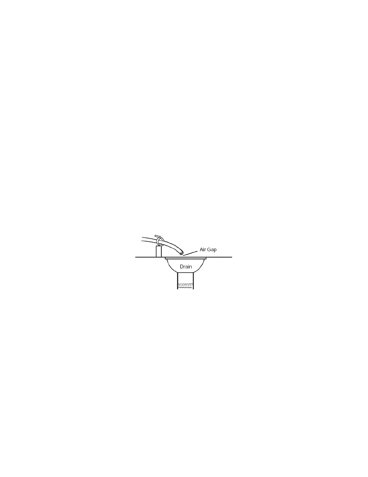
Figure 3
• The control valve drain connection is 3/4" npt.
• Never decrease the drain piping size to below ¾”
• Maximum drain line length is 30 feet.
• Maximum drain line height is 6 feet above the
control valve.
• The drain line must be piped to an open airgap
(See Figure 3)
• Always follow local plumbing codes.
UNDER NO CIRCUMSTANCES SHOULD THERE BE A DIRECT
CONNECTION WITH SANITARY SEWAGE FACILITIES.