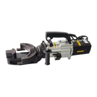
The RB16 25 32 Portable Rebar Bender is a specialized tool designed for bending concrete reinforcing bars. It is primarily intended for straightening deformed rebar but can also be used to bend straight rebar. The machine emphasizes performance, efficiency, and reliability.
Function Description:
The rebar bender operates hydraulically, allowing for precise and controlled bending of rebar. It features two operating modes: PUSH and PULL, selected by a mode control lever. In PUSH mode, the piston advances, while in PULL mode, the piston retracts. The movement of the piston is limited by a safety valve to prevent overheating; users should release the trigger switch once the piston reaches its travel limit. The tool is designed to be used in confined spaces due to its dual operating modes.
Important Technical Specifications:
The manual provides specifications for several models: NRB-32, NRB-25, NRB-22, and RB-16.
| Model |
Voltage (±5%) |
Wattage |
Dimensions (mm) |
Weight |
Max. Rebar Diameter |
Min. Rebar Diameter |
Max. Rebar Hardness |
Bending Speed |
| NRB-32 |
100/115V or |
1600 W |
560260200 |
24 Kg |
32 mm |
4 mm |
Tensile strength |
5.0 - 8.0 sec. |
|
220-240V AC |
|
|
|
|
|
650N/mm² |
|
| NRB-25 |
100/115V or |
1500W |
560170220 |
16 Kg |
25mm |
4mm |
Tensile strength |
5.0s |
|
220-240V AC |
|
|
|
|
|
650N/mm² |
|
| NRB-22 |
100/115V or |
1200W |
580170210 |
16KG |
22mm |
4mm |
Tensile strength |
4-5S |
|
220-240V AC |
|
|
|
|
|
650N/mm² |
|
| RB-16 |
100/115V or |
900W |
600170200 |
15KG |
16mm |
4mm |
Tensile strength |
4-5s |
|
220-240V AC |
|
|
|
|
|
650N/mm² |
|
The maximum rebar hardness for all models is a tensile strength of 650N/mm².
Usage Features:
- Safety Precautions:
- Usage: Exclusively for concrete reinforcing bars.
- Restricted Materials: Do not bend very hard rebar, or rebars harder, thicker, or thinner than specified, as this can damage the tool and cause the rebar to break.
- Eye Protection: Always wear safety goggles, safety glasses with side shields, or a face shield.
- Safety Barriers: Erect safety screens to protect co-workers from flying rebar ends, especially when working in high places.
- Electric Shock: Avoid handling the bender with wet hands or using it in rain/damp conditions. Be aware of all power lines and electrical circuits.
- Unplugging: Disconnect from the outlet when not in use, before cleaning, adjusting, or servicing. Always ensure the switch lock is OFF before plugging in.
- Environment: Do not use in the presence of flammable materials (e.g., paint, thinner, petroleum products, adhesives). Ensure the operator has an unobstructed view of the cutter, rebar, and surrounding area.
- Apparel: Wear proper attire; avoid loose clothes, dangling objects, or jewelry. Restrain long hair. A safety helmet and rubber-soled boots are recommended. Be careful with safety gloves to prevent them from getting caught in moving parts.
- Visitors: Keep visitors at a safe distance from the work area to ensure their safety and prevent operator distraction.
- Pre-Use Checks:
- Check oil level.
- Inspect bender blocks and ensure their bolts are tight.
- Verify the power source is appropriate for the bender. Incorrect voltage (too high or too low) can damage the motor or reduce power. Never use DC power.
- Ensure the power supply is properly earthed to prevent electric shock.
- Check that the cord is undamaged and the plug is not loose. If using an extension cable, ensure it is undamaged and of the proper thickness for its length (refer to the provided table for cable length, AWG, and nominal diameter).
- Before plugging in, confirm the switch lock is OFF.
- Warm-Up: In cold weather, warm up the unit for 30-60 seconds to allow the hydraulic oil to reach proper viscosity. Pull the trigger switch to extend the piston to its full stroke, then release. Repeat 15-20 times.
- Points of Attention:
- Do not cover air vents to prevent motor overheating and burnout.
- If hydraulic oil exceeds 70°C (158°F), power will drop. Allow the unit to cool before resuming operation, especially in summer.
- If power drops and the motor is unusually hot, check the carbon brushes.
- Operating Modes (PUSH & PULL):
- TO PUSH: Advance or retract the piston to a suitable starting position. Set the mode control lever to "A". Fit the rebar as shown in the diagram. Pull the trigger switch until the desired angle is achieved.
- TO PULL: Set the hook in the correct starting position. Ensure the mode control lever is in the "B" position. Fit the rebar as illustrated. Pull the trigger switch until the desired angle is attained.
- Ensure the rebar is properly fitted in the hook and against the rollers.
- The interior straightening/bending angle varies with rebar diameter and operating mode due to the limited piston stroke.
Maintenance Features:
- General Care:
- Inspect the bender before each use.
- Keep the handle dry, clean, and free from oil/grease.
- Keep the housing and piston free of dirt and iron filings.
- Check for loose or missing screws/bolts.
- Inspect the switch, cord, plug, and any extension cable regularly.
- Storage: Store the bender and accessories in a dry place inaccessible to unauthorized persons.
- Cleaning:
- Clean the bender daily, preferably immediately after use.
- Wear gloves to protect hands from metal splinters.
- Do not use an air-gun for cleaning, as blasting with air can cause metal filings and/or dust to enter eyes and the respiratory system.
- Disconnect the unit.
- Wipe or brush away all dirt and metal filings, paying particular attention to the lower half of the piston where dirt accumulates.
- Oil-Level Check:
- As the bender is hydraulically operated, check the oil level frequently, preferably daily. Low oil levels lead to a drop in pressure and loss of bending power.
- Procedure:
- Oil should be warm but not hot. Warm up the unit if cold.
- Adjust the stopper and make three or four cuts, noting the rebar's breaking point.
- Pinch a short piece of rebar, stopping just before it breaks off. Unplug the unit.
- With the partially severed rebar in place, turn the unit over so the oil-plug is uppermost. Allow to cool if hot.
- Remove the oil-plug and seal-washer (packing). Never remove the oil-plug when the unit is hot, as oil may spurt out.
- Check that the oil level is even with the bottom of the plug hole (i.e., the pump case is full to the brim). If the oil level is too low, top up with 20-weight hydraulic oil with anti-foam and anti-abrasion properties (ISO viscosity grade VG46, e.g., Shell Oil Tellus 46, Mobil Oil DTE-25, or Esso Uni Power SQ46).
- After topping up, extract air from the system. Gently tilt the cutter lengthwise and return it to a level position. Top up again and tilt in the opposite direction. Repeat until all air is extracted. The bender cannot function properly if oil contains air bubbles.
- Replace the seal washer (packing) and plug. Connect the cutter to the power source and completely sever the rebar.
- Oil-Change:
- Change the hydraulic oil at least once a year, or sooner if it appears dirty.
- Procedure:
- Unplug the unit. Remove the oil-plug and packing.
- Turn the bender over and drain oil into a suitable receptacle.
- Once oil stops draining, tilt the unit to the rear to drain oil trapped in the piston housing.
- Tilt the unit in the opposite direction to empty residue from the pump case.
- With the drain-hole uppermost, slowly fill the unit with fresh oil. Replace the plug and lightly tighten.
- Connect the unit to the power source and advance the piston two or three times.
- Unplug the unit and remove the oil-plug. Top up the oil-level and replace the plug.
- Finally, follow the oil-level check procedure (steps 2-8).
- Dispose of hydraulic oil in accordance with local regulations; do not pour into the sea, a river, a lake, or drains.
- Bolt Tightness:
- Check the tightness of all bolts weekly, or after every 500 bends, especially those securing the housing to the cylinder. Loose bolts will result in a loss of power.
- Carbon Brushes:
- Inspect the two carbon brushes at least once every two months (nominal brush life is 200 hours).
- Worn brushes lead to power loss, cause the motor to run hot, and irreparably damage the armature's commutator.
- Procedure:
- Disconnect the unit.
- Unscrew both brush caps and pull out the carbon brushes.
- Replace brushes if they are less than 6 cm in length.