2
3
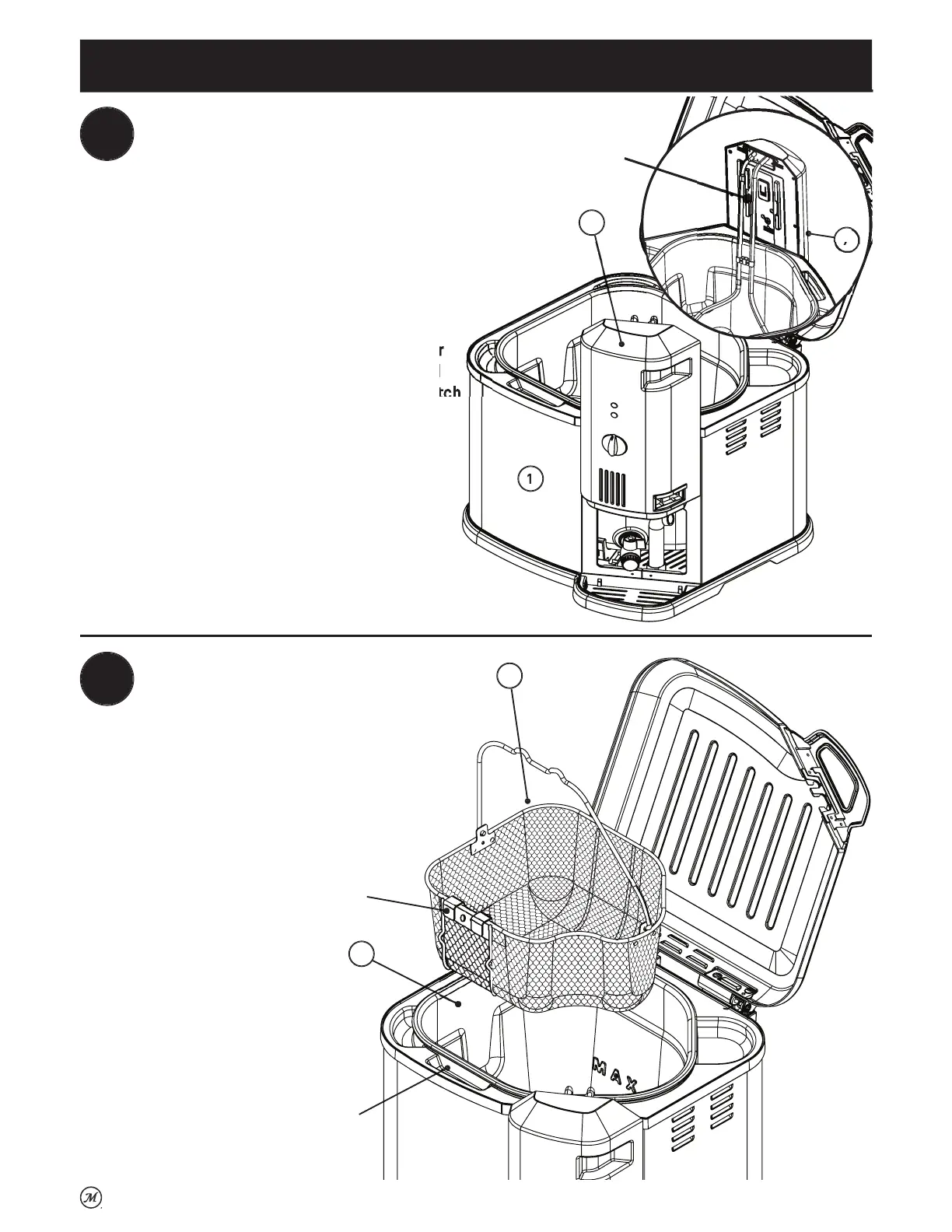
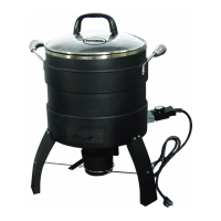
Slide control panel and element
7
down onto mountin
bracket
shown in step 1
on side of outer shell
1
.
Deslice el
anel de control
el elemento
7
hacia abajo,
hasta la abrazadera de montaje
ue se muestra en el
aso
1
en la
arte lateral de la carcasa exterior
1
NOTE: The control
anel is correctl
attached whe
the heating element is positioned inside the inner
ot. The control
anel must be correctl
attached
for the appliance to operate. A built-in safety switch
on the control panel will prevent the element fro
heatin
if not mounted correctly
NOTA: El panel de control está correctamente fijado
cuando el elemento calefactor está
osicionado
dentro de la olla interna. El panel de control debe
estar correctamente fijado para que el artefacto
pueda funcionar. Un interruptor de se
urida
integrado en el panel de control evitará que el elemento
li
nt
i n
t
n
m
l
rr
t
m
nt
.
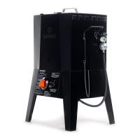
Place basket
3
inside of inner pot
4
.
Colo
ue el cesto
3
dentro de la olla interna
4
.
Assembly | Ensamblaje
AFETY
WIT
NTERRUPT
R DE
E
URIDAD
DRAIN
LIP
SUJETADOR DE
URRID
R
RAIN
LIP M
UNTIN
H
LE
RIFI
I
DE M
NTA
E DEL
UJETAD
R DE E
URRID
R