Fig. 15 Fig. 16
Fig. 18
Fig. 20
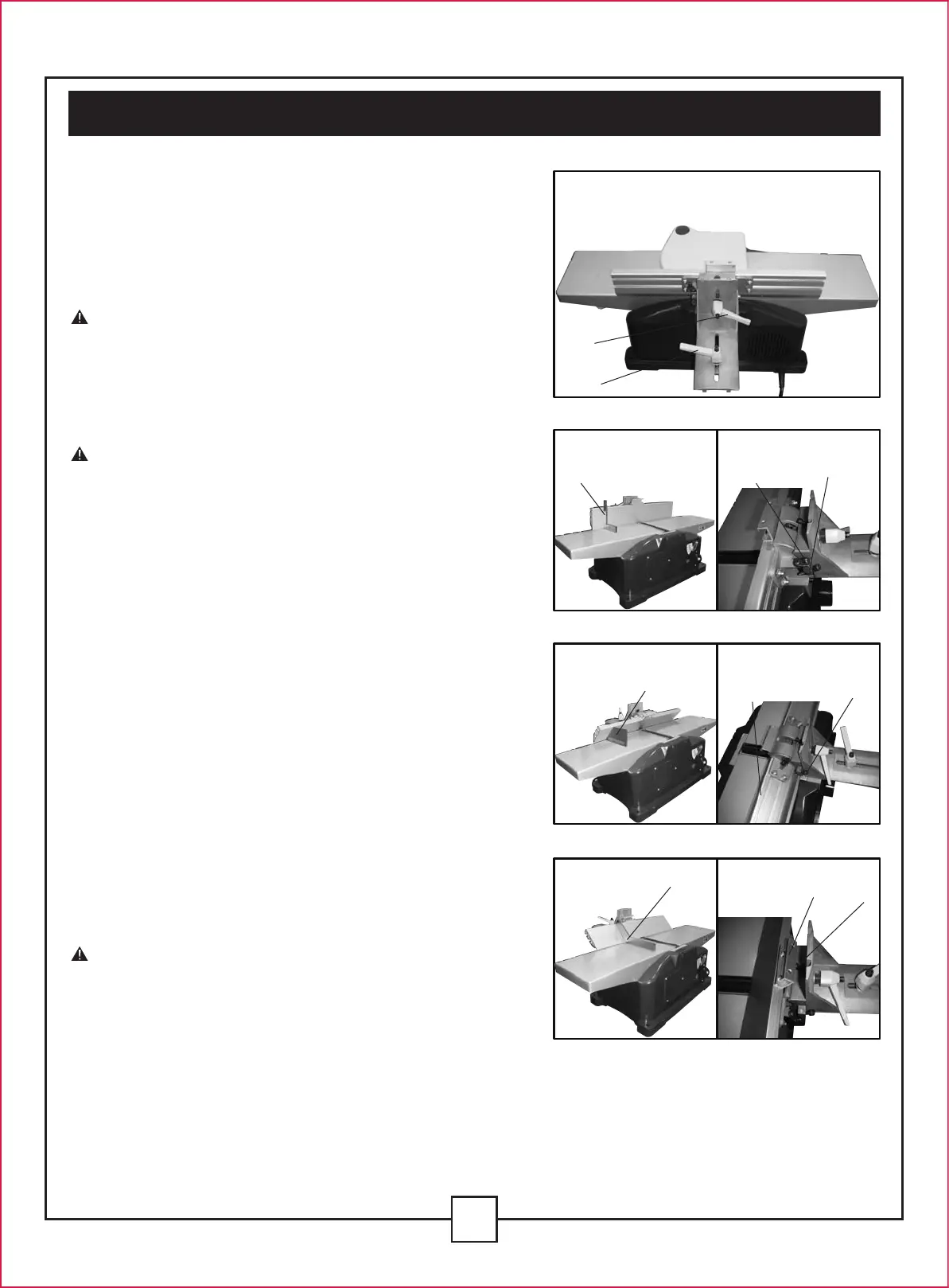
FENCE ADJUSTMENTS (Fig. 14-20)
The fence can be moved across the table and can be
tilted up to 45
o
, as follow:
- To move the fence across the table, loosen clamping
lever (A) (Fig. 14). Slide the fence to the desired position
on the table and tighten the clamping lever (A).
NOTE: Clamping lever (A) is spring loaded and can
be repositioned by pulling up on the lever and
repositioning it on the nut located underneath the lever.
- To tilt the fence, loosen clamping lever (B) (Fig. 14),
and tilt the fence to the desired angle. Then tighten
the clamping lever (B).
NOTE: Clamping lever (A) is spring loaded and can
be repositioned by pulling up on the lever and
repositioning it on the nut located underneath the lever.
- The fence features adjustable positive stops at the
used fence positions of 90
o
and 45
o
to the left and right.
To check and adjust the positive stops, proceed as
follows:
• Place a square (C) (Fig. 15), on the table with one end
of the square against the fence as shown. Adjust the
fence until it is exactly 90
o
to the table.
Turn set screw (D) (Fig. 16) until it contacts stop (E).
• Using a 45
o
square to the right (F) (FIg. 17), tilt the table
to the 45
o
position and make sure the fence is 45
o
to
the table. Adjust the fence if necessary.
Turn set screw (G) (Fig. 18), until it contacts fence (H).
• Using a 45
o
square to left (I) (Fig. 19), tilt the table
to the 45
o
position and make sure the fence is 45
o
to
the table. Adjust the fence if necessary.
Turn set screw (J) (Fig. 20), until it contacts the limiting
block (K).
- These positive stops enable you to rapidly position
the table to the 90
o
and 45
o
settings.
CAUTION: MAKE SURE THE FENCE IS IN LEVEL
CONTACT WITH THE SURFACE OF THE OUTFEED
TABLE。
14
V. Assembly and adjustments (continued)
B
A
C
D
F
I
K
J
G
E
H
Fig. 14
Fig. 17
Fig. 19
 Loading...