headline bars
continuation tabs
notes
warnings
headline bars
continuation tabs
notes
warnings
headline bars
continuation tabs
notes
warnings
13
headline bars
continuation tabs
notes
warnings
headline bars
continuation tabs
notes
warnings
headline bars
continuation tabs
notes
warnings
OPERATING INSTRUCTIONS
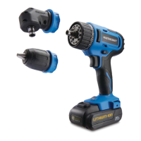
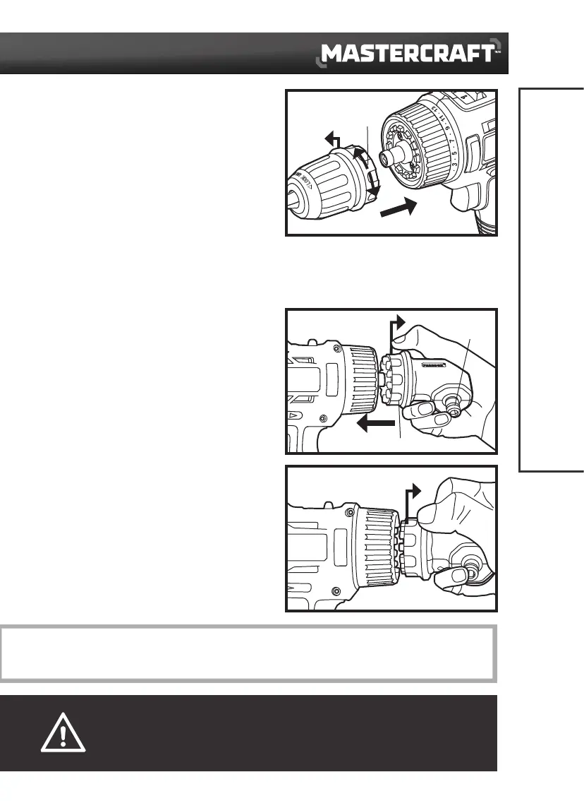
INSTALL THE DRILL CHUCK
(fig 2)
1. Set the direction-of-rotation selector in the OFF
(centre) positon.
2. Pull the unlocking ring forward (1) and press the
drill chuck all the way onto the hex chuck of the
drill/driver (2).
3. Release the unlocking ring. Check that the drill
chuck is locked in position.
REMOVE THE DRILL CHUCK
(fig 2)
1. Set the direction-of-rotation selector in the OFF (centre) positon.
2. Pull the unlocking ring forward and remove the drill chuck.
INSTALL THE RIGHT-ANGLE ADAPTOR
(
fig 3a
)
1. Pull the unlocking ring forward (1) and hold the
hex chuck of the right-angle adaptor with your
finger to prevent the hex chuck from rotating.
2. Rotate and press the right-angle adaptor onto the
drill/driver (2).
3. Release your finger while still holding the
unlocking ring, then the right-angle adaptor can
be locked in the required angular position by
rotating the right-angle adaptor.
4. Release the unlocking ring and check that the
right-angle adaptor is locked into the correct
position.
REMOVE THE RIGHT-ANGLE ADAPTOR
(
fig 3b
)
Pull the unlocking ring forward (1) and remove the
right-angle adaptor from the drill/driver.
1
fig 2
Unlocking
ring
CAUTION!
• Before carrying out any work on the drill/driver, lock the variable-speed trigger switch by placing the
direction-of-rotation selector in the OFF (centre) position.
NOTICE: The right-angle adaptor facilitates working in places which are difficult to access. The right-angle adaptor can be
locked in different 30° angular positions.
1
2
1
fig 3b
1
2
fig 3a
Hex chuck
Unlocking ring