2017 OWNERS MANUAL / 268
forward.
• It should easily slide about 1/2” before catching on a small, raised
feature intended to keep the tower from sliding out too easily and
the operator losing control of it.
• A small push or bump with the palm of your hand should be
enough to fully disengage the locking clip
• Be careful not to push/strike the tower hard enough that it falls
on you. Very light pressure with your other hand on the upright
should prevent this from happening. Too much pressure will pos-
sibly prevent the clip/foot from sliding and disengaging.
• Repeat on the other side.
• Remove tower from the boat.
If desired, the locking hook can be stowed in the tower mounting base.
• Push the hook forward in its groove, until it will fold sideways
towards it stowed position.
• Collapse the locking clip in order to completely stow.
Installation is essentially the reversal of the removal, assuming the
hook is stowed:
• Collapse locking clip and rotate out of the stowed position.
• Spring load will push the hook to the back of its groove. Note:
Take care that you don’t pinch your fingers!
• Place tower in front of the hooks in the upright position.
• Pull each tower foot back into the hook.
• Rotate tower back to hook up navigation light.
• Connect the light wires.
Do not plug the wires together. This will act as a direct short if the
light switch is turned on, resulting in a tripped circuit breaker or a
blown fuse. The male connector should be inserted in the groove
in the plastic below the deck mount. Groove will be on the forward
side of the hole.
• Looping the wires up so they create pressure against the deck/
hole will provide additional resistance to them from falling down.
• DO NOT PUSH THE WIRES ALL THE WAY DOWN! If this happens,
the side access panel will have to be removed to re-route them
through the access hole.
• Ensuring the wires are clear, stand the tower all the way back up
to its normal operating position.
• From the back side of the tower, push the base of the tower leg
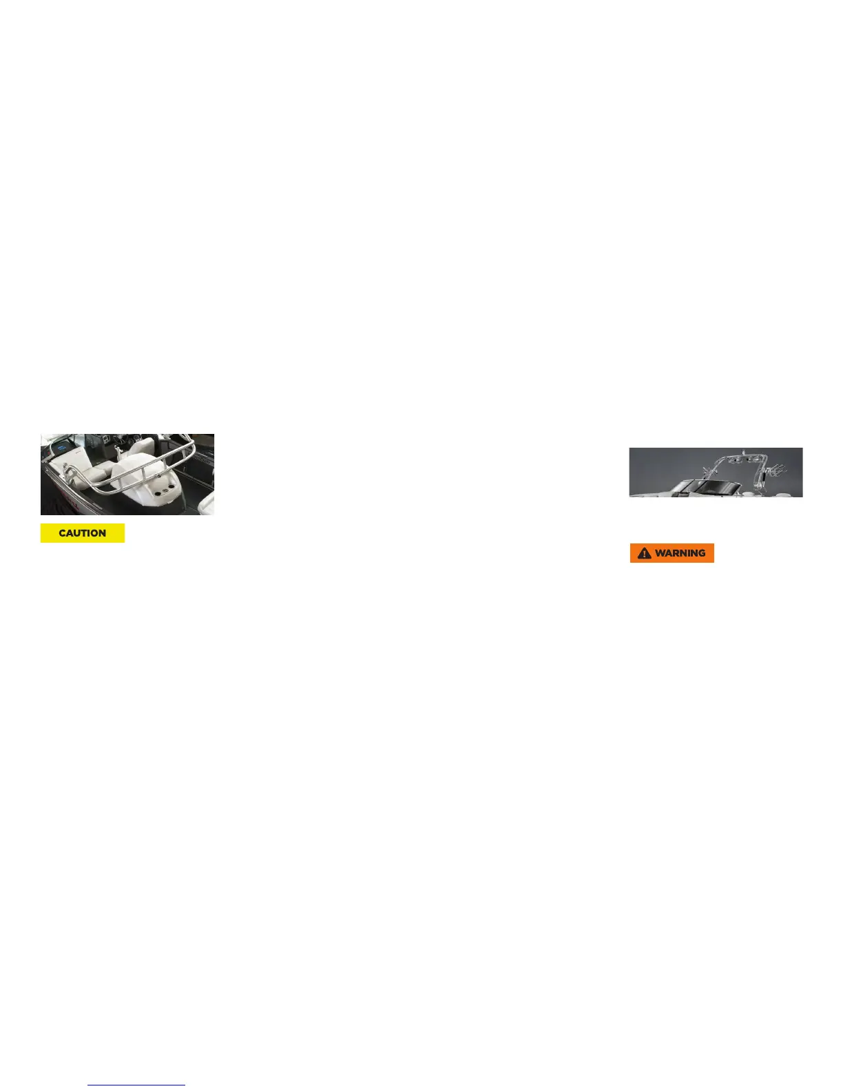
Lowering and Raising the ZFT4 Tower
The ZFT4 tower can be manually raised or lowered for storage
or easier towing. The locking mechanisms located at the pivot
point on each side of the tower are pulled out to allow the tower
to raise or lower.
Always reinstall the locking mechanism on both sides of the
ZFT4 tower immediately afer raising or lowering the tower.
Failure to do so could result in damage to the tower or collapse
of the tower, which could result in serious injury or death.
Depending upon the total aggregate weight of the tower and any
installed accessories, it is advisable to have a second person assist
in steadying the tower during the raising and lowering process on
the ZFT4 tower.
• Feed all of the excess wires and connectors below the deck
through the access hole.
• The remaining wire should be straight.
• Slowly stand the tower back up, keeping an eye on the wires and
ensuring they don’t get pinched.
• Make sure that both tower feet/hooks are all the way to the back
of the groove. If they are not, the hand knob threads won’t be
aligned.
• Get one hand knob started and threaded much of the way in.
NOTE: If the threads don’t start easily, it could be that the tower
is in a slight bind. Back o the hand knob or lightly bump the
tower/foot to free the bind before continuing to tighten.
• If you have two (2) people, starting and tightening together is
easiest.
• Start the second hand knob and tighten until it is snug.
• On the other (original side), put a moderate amount of forward
pressure on the tower header while torquing the hand knob tight.
• Repeat the previous step on the second side. Note: These last
two steps are important to ensure that the tower does not come
loose during operation.