Do you have a question about the MasterForce 241-0725 and is the answer not in the manual?
Always wear eye protection conforming to CSA requirements or ANSI safety standard Z87.1. Use hearing protection.
Wear a dust mask designed for power tool use in dusty environments. Understand chemical hazards from dust.
Use proper circuit protection. Tool is 120V AC, 15 Amp circuit protected by time-delayed fuse or circuit breaker.
Keep work area clean, lit. Avoid explosive atmospheres. Keep children/bystanders away. Distractions cause loss of control.
Match plugs to outlets. Avoid body contact with earthed surfaces. Do not expose to rain/wet. Do not abuse cord.
Stay alert, use common sense. Do not use when tired/under influence. Use PPE. Prevent unintentional starting. Do not overreach.
Dress properly: no loose clothing/jewelry. Keep hair/clothing away from moving parts. Ensure dust extraction is connected.
Do not force tool. Use correct tool. Do not use if switch is faulty. Disconnect power before adjustments. Store out of reach of children.
Check for misalignment, binding, breakage. Have damaged tools repaired before use. Keep cutting tools sharp.
Have tool serviced by qualified person using identical replacement parts.
Read manual, understand applications, limitations, and hazards. Follow rules to reduce shock, fire, injury risk.
Always wear safety goggles (not glasses) complying with ANSI Z87.1. Non-compliant eyewear can cause serious injury.
Always use a safety shield, hearing protection, and dust mask when drilling concrete.
Secure workpiece. Keep hands clear of bit. Ensure chuck is tight and bit is centered.
Jog switch to check wobble. Ensure spindle stops before changing bits. Do not use fly cutters.
Keep cord clear of work area. Use heavy enough gauge cord for amperage and length. Use for outdoor use if needed.
Ensure cord is wired correctly. Replace damaged cords. Use separate circuit, 14-gauge wire, protected by 15A fuse/breaker.
Install auxiliary and D handles for better control. Auxiliary handle threads on, D handle screws in.
Controls drill rotation direction. Middle position is neutral. Do not change while chuck is turning.
Squeeze trigger to start. Speed varies with trigger depth. Release to stop. Avoid slow speed for extended periods.
Pre-set RPM using dial. Engage lock-on button for continuous operation at set speed. Adjust speed clockwise/counter-clockwise.
Remove plug. Open chuck jaws. Insert bit fully. Tighten chuck key clockwise. Ensure bit is centered.
Ensure bit is centered and jaws grip. Mark smooth surfaces. Secure workpiece with vice/clamps.
Check bit lock and forward position. Hold drill firmly. Apply light pressure. Use oil for metal drilling.
Do not force bit or apply sideways pressure. Release trigger if bit jams. Determine reason for jamming.
Use correct bit size. Fasten bit securely. Use slower speeds for soft material. Hold drill firmly with both hands.
Remove plug. Insert hex key, tighten jaws. Tap key clockwise with mallet to loosen screw (left-hand thread).
Remove hex key. Open jaws. Remove chuck screw (left-hand thread). Tap key counter-clockwise to loosen chuck.
Insert hex key, tighten. Tap clockwise with mallet to tighten on spindle. Tighten chuck screw (counter-clockwise).
Unplug tool. Remove brush cap. Pull out spring/brush assembly. Insert new assembly. Re-thread brush cap.
Use identical parts. Clean with cloth. Do not use solvents. Do not abuse or modify tools.
Bearings are pre-lubricated for life. No further lubrication is required.
Return tool with original receipt to Menards within 90 days for a refund.
Covers defects in material/workmanship for 3 years. Excludes abuse, misuse, expendable parts, commercial use.
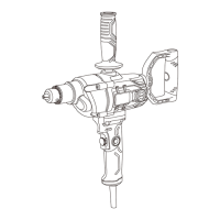
This document describes the Masterforce 5/8" Drill/Mixer, a versatile power tool designed for drilling and mixing applications. The manual provides comprehensive instructions for safe operation, assembly, and maintenance, ensuring users can effectively utilize the tool while minimizing risks.
The Masterforce 5/8" Drill/Mixer is primarily designed for drilling holes in various materials and for mixing substances. Its robust construction and powerful motor make it suitable for both light-duty and heavy-duty tasks. The drill features a 5/8" keyed chuck, allowing for secure attachment of a wide range of drill bits and mixing accessories.
A key functional aspect of this tool is its variable-speed ON/OFF trigger switch, which allows for precise control over the rotational speed. This is particularly useful when working with different materials or when performing tasks that require varying levels of power and speed, such as starting a hole or mixing viscous liquids. The variable speed functionality is further enhanced by a speed control dial, which enables users to pre-set a desired RPM. This feature is especially beneficial for prolonged operations where a consistent speed is required, or for tasks that demand specific speed settings for optimal results.
The drill also incorporates a forward/reverse switch, conveniently located above the trigger switch. This allows the user to easily change the direction of rotation, which is essential for removing drill bits from a workpiece, backing out screws, or for specific mixing applications. The ability to reverse direction adds to the tool's versatility, making it suitable for both driving and removing fasteners, as well as for various mixing techniques.
For extended operations, the drill is equipped with a lock-on switch. This feature allows the user to lock the ON/OFF switch in the ON position, eliminating the need to continuously hold down the trigger. This reduces user fatigue during prolonged drilling or mixing tasks, improving comfort and control. To disengage the lock-on feature and turn off the drill, the user simply squeezes and releases the trigger switch.
The tool's design emphasizes user control and safety. It includes an auxiliary handle and a swiveling "D" handle, both of which are crucial for providing additional control and stability during heavy drilling or mixing operations. These handles allow for a firm, two-handed grip, which is vital for managing the torque generated by the drill, especially when working with larger bits or dense materials.
Before using the drill, users are instructed to read and understand the entire manual, including all safety rules and operating instructions. This ensures familiarity with the tool's applications, limitations, and potential hazards.
Proper maintenance is crucial for the longevity and safe operation of the Masterforce 5/8" Drill/Mixer. The manual outlines specific maintenance procedures and general care guidelines.
By following these detailed instructions for function, usage, and maintenance, users can ensure the safe, efficient, and long-lasting performance of their Masterforce 5/8" Drill/Mixer.
| Voltage | 20 V |
|---|---|
| Cordless | Yes |
| Battery Type | Lithium-Ion |
| Max Torque | 500 in-lbs |
| Chuck Size | 1/2 inch |