INSTALLATION
10 February 2010 / Chargemaster 12/25-3, 24-12-3 / EN
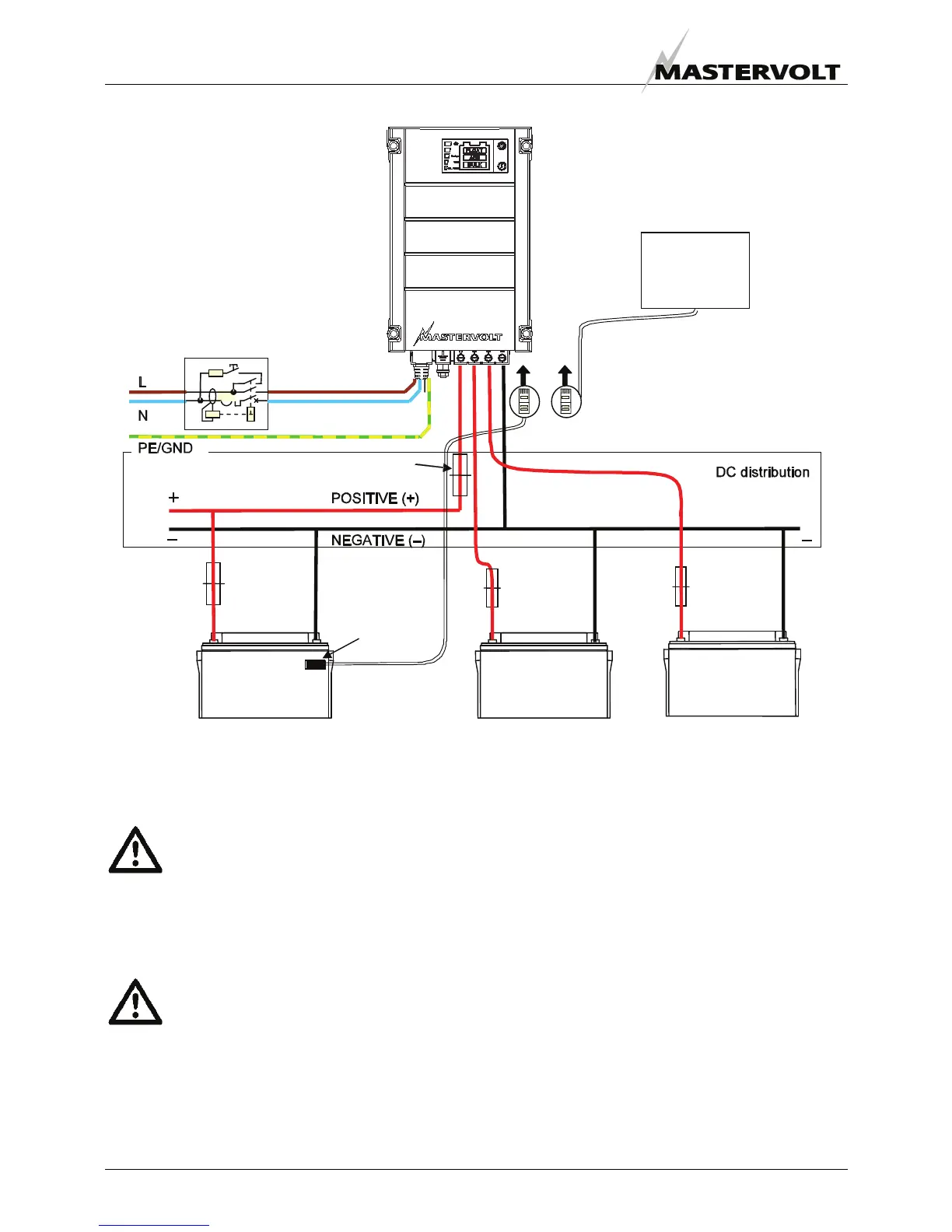
4.6.1 Connection example
4.7 COMMISSIONING AFTER INSTALLATION
CAUTION! Check the polarity of all wiring
before commissioning: positive connected to
positive (red cables), negative connected to
negative (black cables).
If all wiring is OK, place the DC-fuse(s) of the DC-
distribution to connect the batteries to the Chargemaster.
WARNING
When placing this fuse, a spark can occur,
caused by the capacitors used in the
Chargemaster. This is particularly dangerous
in places with insufficient ventilation, due to
the gassing of the batteries an explosion can
occur. Avoid having flammable materials
close by.
Now the Chargemaster is ready for operation. After
switching on the AC power supply the Chargemaster will
initiate the charging process.
4.8 DECOMMISSIONING
To put the Chargemaster out of operation, follow these
instructions in order of succession:
1 Switch Off the AC supply for the Chargemaster
2 Remove the DC-fuse(s) and disconnect the batteries.
3 Disconnect the AC.
4 Disconnect all the wiring.
4.9 STORAGE AND TRANSPORTATION
When not installed, store the Chargemaster in the original
packing, in a dry and dust free environment.
Always use the original packing for transportation. Contact
your local Mastervolt Service Centre for further details if
you want to return the apparatus for repair.
Temperature
sensor
BATTERY
BANK 1
BATTERY
BANK 2
BATTERY
BANK 3
DC fuse
Battery
fuse
Battery
fuse
Battery
fuse
AC Input
RCD
Figure 6: installation example of the Chargemaster
This schematic is to illustrate the general
placement of the Chargemaster in a
circuit. It is not meant to provide detailed
wiring instructions for any particular
electrical installation.
MasterBus
network,
see chapter 5.
 Loading...