5
INSTALLATION
WIRING AND CONNECTIONS (see also chapter 12)
When connecting any auxiliary equipment and/or a batte-
ry isolator, proceed as follows:
• switch off the charger;
• switch off the AC mains or generator supply;
• isolate the DC distribution from the battery.
Battery wires
Keep the cable connection between charger and battery
as short as possible. Use for the connections between the
charger and battery or DC distribution the cable which is
con-nected to the charger. If the lenght is not sufficient,
then replace the whole cable for a longer one. In such a
case, use cables with a larger diameter. If possible use
coloured battery cables. I f this is not possible, mark the
plus and the minus cables with coloured insulating tape,
e.g. red for plus and blue for minus. Use the following
diameters:
lenght up to 3 meter lenght above 3 meter
6 qmm / AWG 9 10 qmm / AWG 7
Connection of main batteries
The M5 cable connectors have to be connected to the
charger. The minus cable (blue) on the -battery (min con-
nection) of the battery charger. The plus cable (red) on the
+ main battery (plus-connection) of the charger.
The M8 cable connectors have to be connected to the
bat-tery or the DC distribution. The min cable (blue) on the
min-connection of the battery or DC distribution. The plus
cable (red) on the plus-connection of the battery or DC
distribution.
Reversing the plus and the minus will damage
the charger seriously.
Too thin cables and/or loose connections can
cause dangerous overheating of the cables and/
or terminals. Therefore tighten all connections
well, in or-der to limit as far as possible transition
resistance, and use the battery cables of the correct
diameter.
Connection of cranking battery
The distance between charger and cranking battery de-
termines the required, minimal cable diameter. For cable
lenghts up to 6 meters 2,5 qmm / AWG 13 must be used.
When using long thin cables, it will take proportionately
longer before a crancking battery is entirely charged.
Therefore use, for longer distances, a larger diameter.
The maximum charging current for the cranking battery is
3A. The char-ging current for the main battery will in this
case be 3A less.
• Connect the minus of the cranking battery to the minus
of the main battery.
• Connect the plus of the cranking battery to the “+slave”
plus terminal of the charger (see chapter 12).
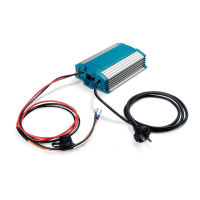
AC power supply
Check the voltage of your IVO charger and power source.
This must be between 90 and 160 VAC.
Connect the power cord of the IVO charger to the mains
or generator.
As soon as the AC plug is connected to the
mains, the charger will function immediately.
The charger has no ON/OFF switch!
CONNECTION OF BATTERY ISOLATORS
If you connect options act as follows:
• unplug and remove the AC wire;
• disconnect the DC side of the battery and charger, first
the battery.
CONNECTING ACCESSORIES
When connecting accessories handle as follows:
• Unplug the AC power cord
• Disconnect all DC Parts
Temperature sensor
Install the temperature sensor in such a way that an
accurate measurement is given of the battery tempera-
ture. The IVO Smart battery charger is equipped with
multiple modular jacks. The sensor can be connected to
any of the modular jacks.
Basic remote control panel
The Basic remote control panel shall be connected by
using a 6-core modular connection cable between the
control panel and the modular analog remote jack.
Standard remote control panel
The standard remote panel shall be connected by using a
6-core modular connection cable between the panel and
the digital remote modular jack. The communication
protocol is based on a quasi RS 232 interface.
Adjustment interface & advanced remote panel
The Adjustment interface & Advanced remote panel shall
be connected by using a 6-core modular connection cable
between the panel and the digital remote modular jack.
The communication protocol is based on a quasi RS 232
interface.
Battery isolator
If two or more batteries or battery sets must be charged
simultaneously, often a battery isolator is used. A battery
isolator isolates the different battery sets from one
another, in order to prevent one discharging the other. A
consequence of the battery isolator is a voltagedrop of
0,7 Volt. This voltage drop can be compensated by
removing a jumper on the front panel of the charger.
 Loading...