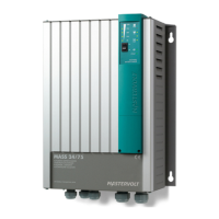
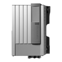
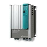
Mass 24/15-2, 24/25-2, 24/25-2 DNV, 24/25-2 (large cabinet) – User and Installation Manual
4.3.2 AC safety grounding
WARNING!
The ground wire offers protection only if the
cabinet of the Mass Charger is connected to the
safety ground. Connect the ground terminal (PE
/ GND) to the hull or the chassis.
CAUTION!
For safe installation it is necessary to insert a
Residual Current Device (earth leakage switch)
in the AC input circuit of the Mass Charger.
4.3.3 DC wiring
Keep the cable connection between charger and batteries
shortest possible. If available, use coloured battery cables.
If this is not possible, mark the plus and the minus cables
with coloured insulating tape, e.g. red for plus and
blue/black for minus. Use the following diameters:
Connection of main batteries
1 Pull the cables through the cable glands of the Mass
Charger.
2 Crimp on the ring M6 terminals to the cable.
3 Connect the cables to the terminals of the Mass
Charger. Pay attention to the polarity, positive on
positive / negative on negative.
4 Integrate a suitable fuse (charger fuse) in the positive
cable. When using a DC distribution with fuses, no
additional fuse is necessary.
5 Cut the cables at length and crimp on the ring
terminals. Connect the cable to the DC distribution or
batteries.
CAUTION
Reversing the positive and negative battery
poles will severely damage the Mass Charger.
Too thin cables and/or loose connections can
cause dangerous overheating of the cables
and/or terminals.
Lay the positive and negative cables next to each other to
limit the electromagnetic field around the cables. The
negative cable should be connected directly to the negative
post of the battery bank or the ground side of a current
shunt. Do not use the hull or chassis frame as the negative
conductor.
4.4 Battery capacity
Always follow the instructions published by battery
manufacturer. The minimum required battery capacity for
Mastervolt gel batteries is as follows:
Minimum required battery
capacity
4.5 Battery isolator
If one or more batteries or battery sets must be charged at
the same time via one output, a battery isolator should be
used. It isolates the different battery sets from one another,
to prevent one discharging the other. A consequence of the
battery isolator is a voltage drop of 0.6 Volt. This voltage
drop can be compensated in two ways:
1 By changing DIP-switch 4 to On (Diode enabled);
2 By using the voltage sense function (see section 4.8).
CAUTION!
Never use both methods. Your batteries will be
overcharged and severely damaged!
Mastervolt offers several Battery Isolators, refer to
www.mastervolt.com.
For a proper installation, see also the connection diagram
included with the battery isolator.
Steps:
1 Check if the Mass Charger, the main supply and the
DC distribution are switched off.
2 Check if the Dc fuses have been removed.
3 Connect the battery isolator(s) using cables with the
same diameter as the battery cables.
4 Compensate the voltage drop over the battery isolator
by changing the setting of dip switch 4 (see fig. 7).
5 Switch on the Mass Charger.
4.6 Connection of second battery (3A output)
The battery chargers are standard equipped with a second
charge output of 3A in order to give a small second battery
set like a starter battery a maintenance charge. The
maximum charge current of the second output is 3A, which
comes from the main output.
• Use 2.5 to 4 mm
2
cable for connection.
• Connect the minus of the second battery to the minus of
the main battery.
• Connect the plus of the second battery to the +3A
terminal of the Mass Charger (see fig. 7 and 8).
• Integrate a 10A slow blow fuse in the plus cable.
4.7 Temperature sensor
The standard temperature sensor is provided with 6 m cable
and a double-sided tape for easy installation. Determine the