warmest place on the battery set and make it clean and
grease free. Remove the piece of paper from the tape and
stick the sensor on the battery. Plug the modular cable into
a terminal at the right of the Mass Charger (see fig. 7). It is
not necessary to shorten the cable. When you want to
shorten it anyway, please notice the polarity of the plug and
use the old connector as an example.
4.8 Voltage sense
To shorten the charge time substantially, the battery cable
losses can be compensated by using the sense function.
Use 0,75 mm
2
, preferably red and black wire and secure
these with fuses of 2A slow blow. Connect the wires with
the two upper terminals of the green connector at the right
side of the cabinet (see fig. 7). Pay good attention to the
polarity of the wires, red on +S and black on -S. Now
connect the other side of the wires: black on the minus of
the battery and red on the battery side of the Mass Charger
fuse.
4.9 Alarm function
The battery charger is equipped with a potential free
contacts alarm relay, see figure 7. The alarm function has
two modes: standard (factory setting) and DC alarm mode
(continuous mode).
4.9.1 Standard alarm mode
In this mode the relay responds to all fault conditions that
the Mass Charger can detect such as: no AC input voltage,
too low DC voltage, voltage sense failure, temperature
sense failure.
4.9.2 DC alarm mode
To enable this mode a DIP switch setting needs to be
changed (switch 1 and 2 at ON). The alarm now works as a
DC alarm and responds to the battery voltage only.
Note: In the DC alarm mode the electronics stay active
permanently and drain a very small current of ± 25mA, also
when the Mass Charger is switched off.
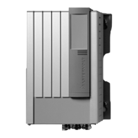
4.10 DNV version
The Mass Charger 24/25-2 is equipped with a larger
connection compartment that offers more room for the
cabling. Refer to section 9.2 Dimensions for more
information on the larger DNV housing.
4.11 Connection of accessories
The battery charger is equipped with several terminals for
accessories. Cable to connect the accessories is not
delivered as a standard. Accessories can be plugged in at
all times. Contact your Mastervolt dealer for an overview of
available accessories.
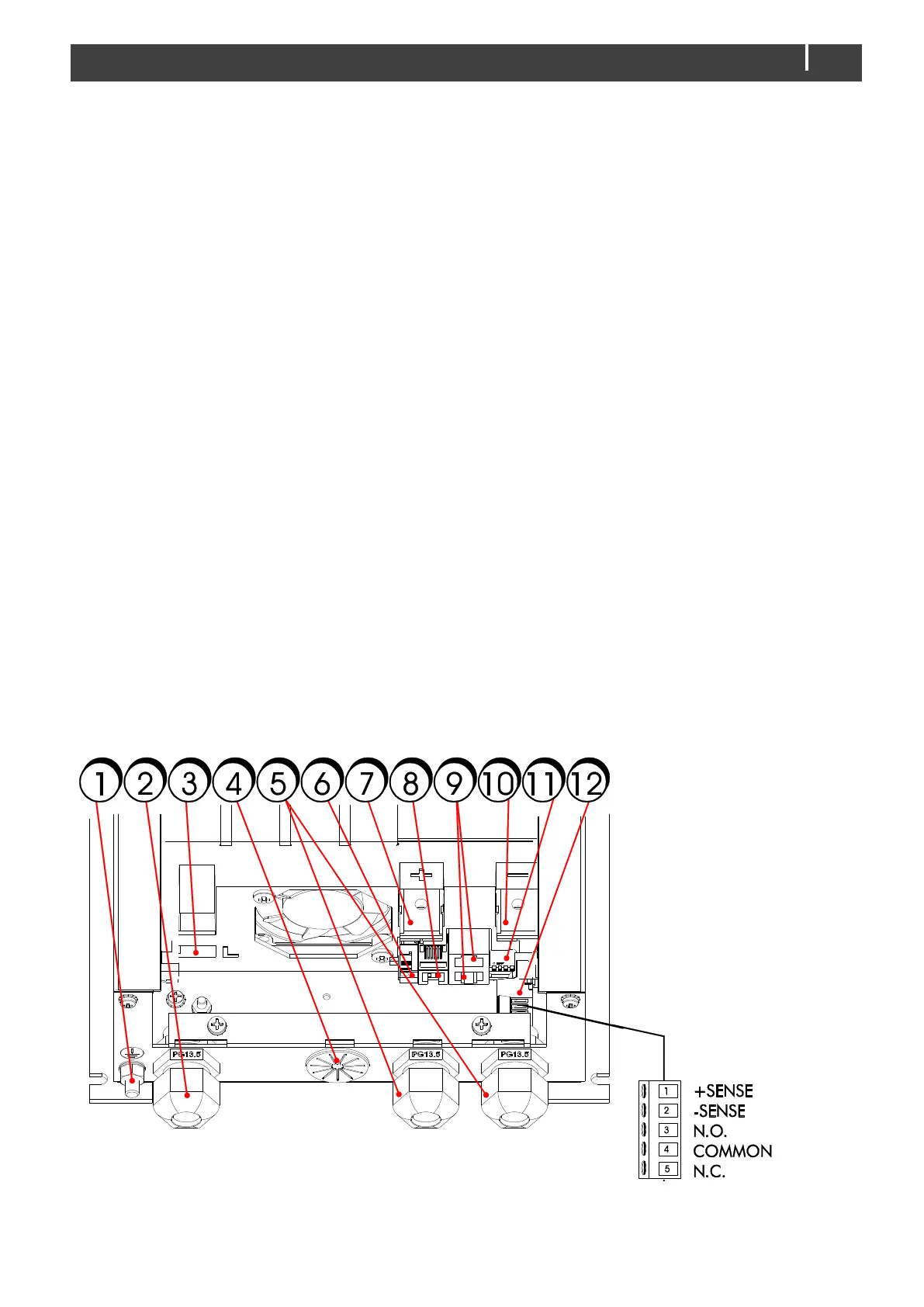
4.12 Overview connection compartment
Figure 7 shows the Mass Charger connections.