5 DIP SWITCH SETTINGS
The Mass Charger settings can be adjusted in two ways:
• By means of DIP switches;
• Via the MasterBus network (by means of a remote
control panel or an interface connected to a PC with
MasterAdjust software); see chapter 7. Some settings,
e.g. Lithium-ion (Mastervolt MLI), can only be changed
in this way.
Note: Once a DIP switch has been set to On, MasterBus
settings are disabled.
CAUTION!
Invalid settings of the Mass Charger can cause
serious damage to your batteries and/or the
connected load! Adjustments of settings may be
undertaken by authorised personnel only!
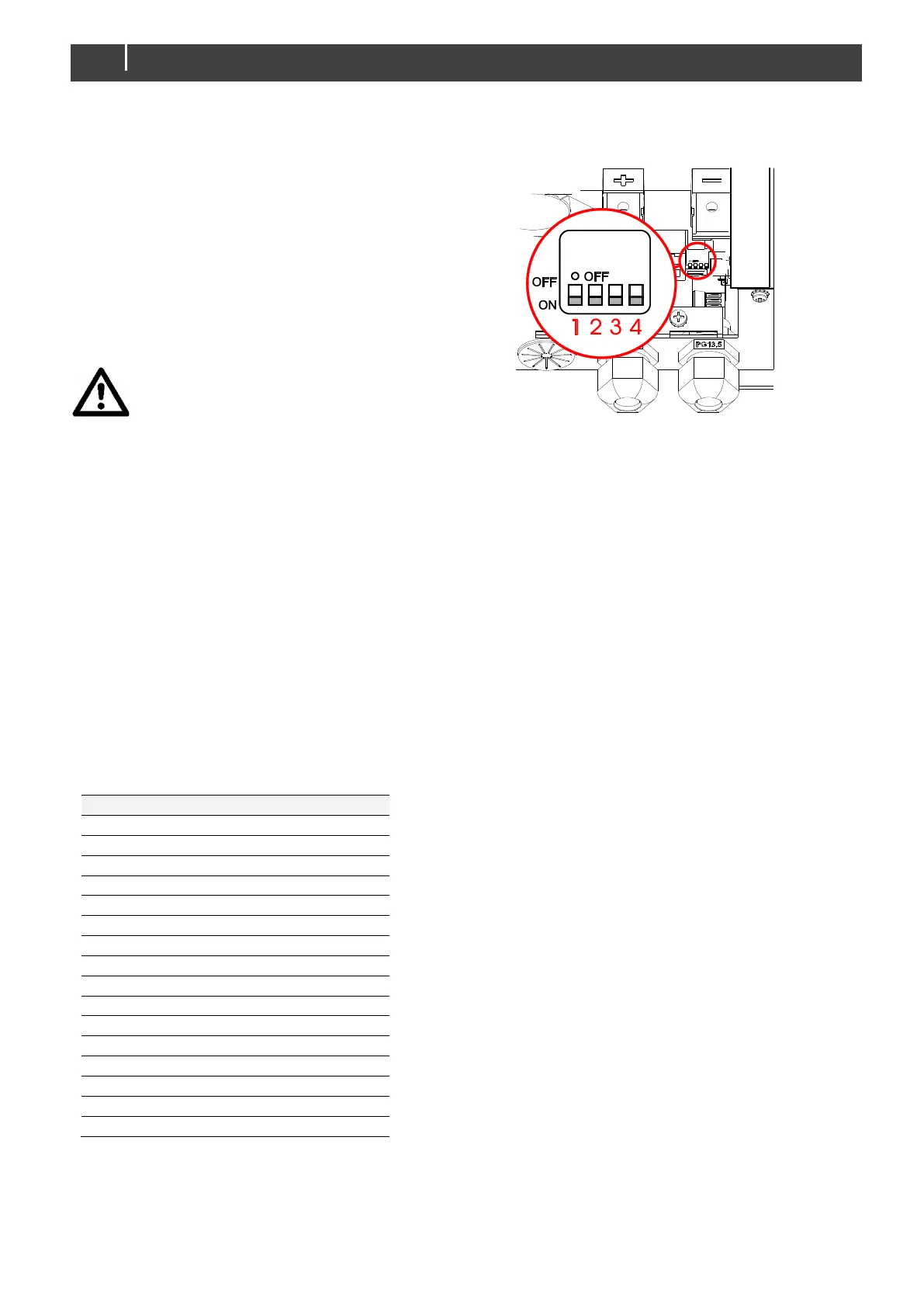
5.1 DIP Switch operation
The Mass Charger has four DIP switches, see figure 9.
These switches are operated by flipping the levers to the
other position, using a small screwdriver.
5.2 DIP switch functions
See the table below for the functional overview of the four
DIP switches
5.2.1 Force Float (DIP switch 1)
For special applications a fixed charge voltage can be
required. The battery charger allows you to change the
three-stage charge program to a single stage program by
activating the function "Force Float", switching DIP switch 1
to "ON".
The charge voltage will be fixed at 26.5V (24V charger)
5.2.2 Traction setting (DIP switch 2)
Setting for traction charging: +0.7 V during bulk and +0.4 V
in absorption for 24 V batteries.
5.2.3 Gel/AGM batteries (DIP switch 3)
Some gel/AGM batteries need a higher float voltage for
optimal charge. Changing the float voltage can by done by
setting DIP switch 3 to "ON". The float voltage will increase
to 27.6V (24V charger).
5.2.4 Diode setting (DIP switch 4)
Setting for +0.6 V voltage compensation in case a battery
isolator is used.