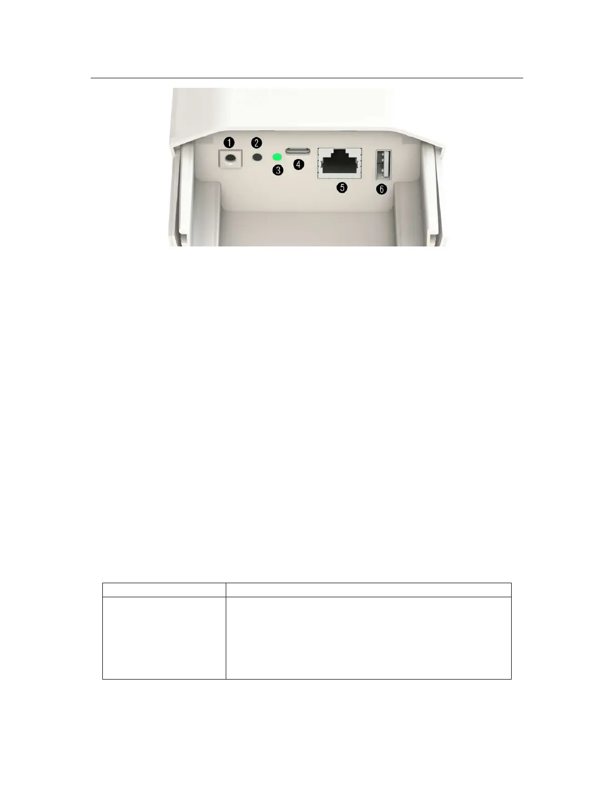
1.3 Interface and Connectors 7
Figure 1.1: Connector panel of the Gateway.
1.3 Interface and Connectors
1.3.1 Connector panel of the Gateway
The get access to the connector box of the gateway the cover needs to be removed. The cover is
fixed with two screws which secure the cover from falling off during strong winds or when or during
interaction with wildlife. After unscrewing the screws and pulling down the cover the connector box
is easily accessible and shown on Figure 1.1. The following interfaces are available:
1. Grounding screw connector - connect this with a copper wire to to ground.
2. User button - used for resetting the Gateway to the factory settings.
3.
RGB LED - this is the status LED. Description of the possible status can be found in Table
1.2.
4.
USB-C connector - can be used for accessing the console terminal and to power the Gateway.
5.
Ethernet connector with passive 24V PoE capability for internet connection and powering the
Gateway.
6. USB-A 2.0 - USB host for connecting extension devices like mass storage.
1.3.2 Led status
The Gateway uses an RGB LED to indicate a various status and its condition. Description of the
LED status can be found in Table 1.2.
LED Color Activity
Flashing Blue Initializing
Steady Blue Connected to Internet, no LoRaWAN is configured
Alternative Blue and Red Device is busy, don’t unplug power
Steady Red No Internet connection or LoRaWAN sever not available
Flashing Green Configuring Box
Steady Green Indicates that the Gateway is connected and working normally
Table 1.2: LED activity of the Gateway