Rev. Descrizione Redatto/Gestito Approvato Cod.Ident. Pagine Data Em.
0.6 Manuale Istruzioni GN UTEC B041.M01.EN 26/47 07/2014
Indicates the type of information read by the analog channel. “Displacement” is selected by default in the gyration
angle channel (*) and specimen height channel; “Load” is selected by default in the applied load channel.
"Weight" in the channel configuration of the weight of the specimen.
Indicates the full scale value of the transducer connected to the analog channel.
The measuring unit chosen for this configuration does not belong to the measuring system set up in the
international settings. In this way the operator is free to enter directly the unit of measure indicated in the technical
specifications of the transducer, without worrying about the overall international settings of the whole system.
Input a value of 5 mm for the gyration angle channel (*) configuration, 12 kN for the applied load channel, and 250
mm for the specimen height channel.
If turned on, it shows the alarm threshold of the analog channel. Select “Off” to disable the alarm control set in the
configuration of all the analog channels.
Indicates the level of the input signal and therefore the amplification gain that must be applied on it before the
acquisition. Please note that low signal levels bring greater amplifications and vice-versa. Select ±5V for all channel
configurations.
(*),
In the channel of the height of the specimen and in the channel of the load applied, Select "±
40mV" in the channel configuration of the weight of the specimen.
Indicates the number of bits used for the data acquisition. By increasing the number of bits, the resolution of the
analog channel and measuring instability will both increase as well (this works also for very small disturbances).
Select 16 bits for the specimen height channel configuration; select 17 bits for the applied load channel
configuration and gyration angle channel configuration.
The analog data are over-sampled compared to what is actually necessary in the application. The samples in
excess can be used to stabilize the reading with variable algorithm which depends to what has been selected in the
parameter “Filter”. For the parameter Filter type one of the following options can be chosen:
1. NONE: no mathematical algorithm is applied for the data acquisition. Only the last of all the signal measured (in
the time range selected for the test) is registered; 2. AVERAGE: it is registered the average value of all the signals
measured in the time range selected for the test; 3. CUSTOM: the signals measured in the time range selected for
the test are damped with a ratio proportional to the value shown in the box “Filter depth Select “AVERAGE” for all
channel configurations. Select "average" in the configuration of all the channels.
(*)The gyration angle is calculated by difference of displacement readings
referred to the radius of the point where the transducer is positioned.
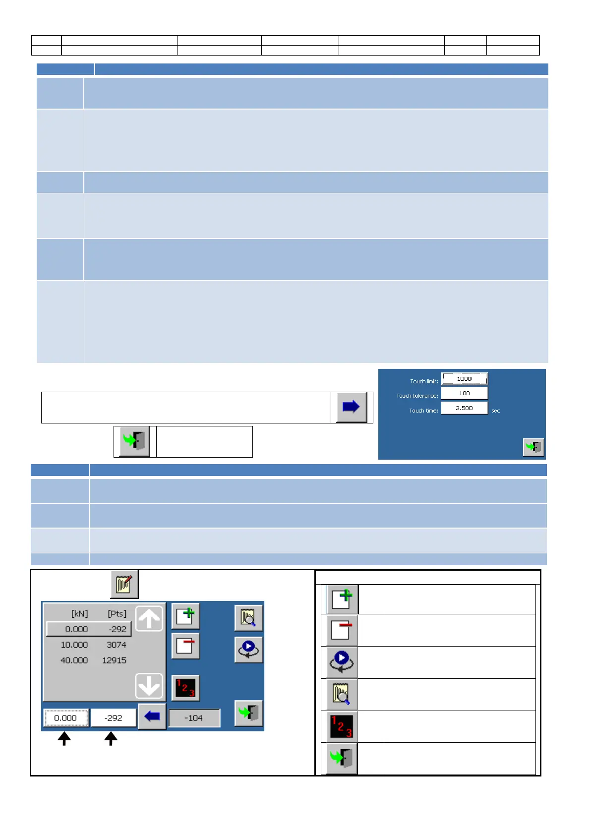
Touch the button to enter the advanced configuration screen
(available only for the specimen height channel).
Command
s:
Screen closure
Automatic
touch limit
It shows the minimum height variation (expressed in points) requested to activate the
specimen touch point.
Manual
touch limit
It shows the minimum height (in points) required to enable overflow checking the specimen during a
manual operation (calibration, calibration verification, ...).
Touch
tolerance
It shows the maximum height variation (expressed in points) requested
by the “touch action” of the
specimen during the time interval expressed in the touch time parameter.
Touch time
It shows the time, expressed in seconds; during this time the “
” parameter is in use.
Touch
the button to enter the calibration screen.
Channel
value of the
selected step
Channel points of
the selected step
Commands
Add a calibration step
Cancel a calibration step
Start the manual activation
Check the calibration
Default initialization of the
calibration steps
Screen closure
 Loading...