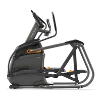
7
A Open HARDWARE FOR STEP 2.
B Slide LEFT PEDAL ARM (5) onto CRANK (6) and attach using
1 BOLT (F) and 1 NUT (G) and tighten to 77.4 Nm / 57 lb-ft.
2 3
Hardware For Step 2
Description Qty
F
G
Bolt
Nut
1
1
A Open HARDWARE FOR STEP 3.
B Carefully pull the CABLE (7) through the UPPER ASSEMBLY (8)
using the LEAD WIRE (9) located inside the UPPER ASSEMBLY (8).
C Attach UPPER ASSEMBLY (8) to MAIN FRAME (2) using 4 BOLTS
(H) and 4 FLAT WASHERS (I) and tighten to 64.5 Nm / 47.6 lb-ft.
D Insert 2 SCREWS (J) into bottom rear of MAIN FRAME (2).
E Insert INCLINE FRAME BOOTS (10) into
bottom area of UPPER ASSEMBLY (8).
Hardware For Step 3
Description Qty
H
I
J
Bolt
Flat Washer
Screw
4
4
2
Note: Be careful not to pinch
any wires while attaching the
upper assembly.
A50 SHOWN
ENGLISH