External Reader Cable
(8 Pin to 15 Pin connector)
Power
Cable
EM Lock Cable
1
2
3
4
5
6
7
8
CN3
9
10
L
OCK RL
Y NO -Yellow
EXIT SWITCH
DOOR STA
TUS-
White
GND-
Black
GND
-
Black
GND LOCK
-
Black
L
OCK RL
Y NC
-
Dark Blue
+12V LOCK
- Red
-White
GND
-
Black
EM L
ock
Diode
LOCK RLY COM -
Light Brown
21
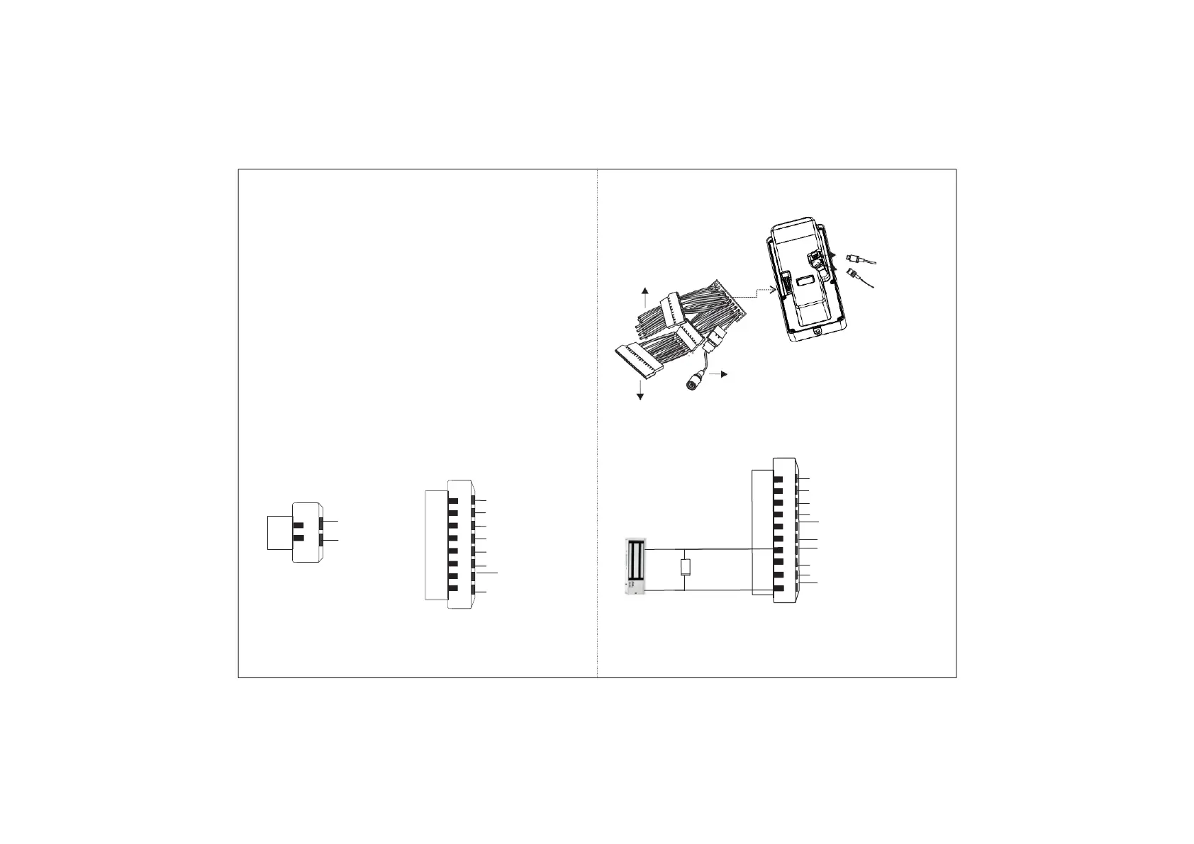
• For Concealed wiring; first draw out sufficient length of the
cables from the hole you have made on the mounting
surface.
• Connect the Power, External Reader and EM Lock cable
assemblies to the 20 PIN connector affixed on the back side
of the COSEC ARGO FACE Unit.
• Connect the Ethernet Cable to the LAN port.
• Connect the micro USB port to the Printer or Broadband
dongle. If required, use a micro USB cable extender.
1
2
CN1
Power
GND- Black
+12VDC IN- Red
1
2
3
4
5
6
7
8
CN2
External Reader
DATA 0- Green
DATA 1- White
BEEPER- Yellow
GREEN LED- Orange
GND- Black
RS 232 RX- Pink
RS 232 TX- Grey
+12V RDR- Red
Connecting the Cables
Micro USB
connector cable
Ethernet Cable
G
F
22
Figure 14
Figure 15
Figure 16