10
9
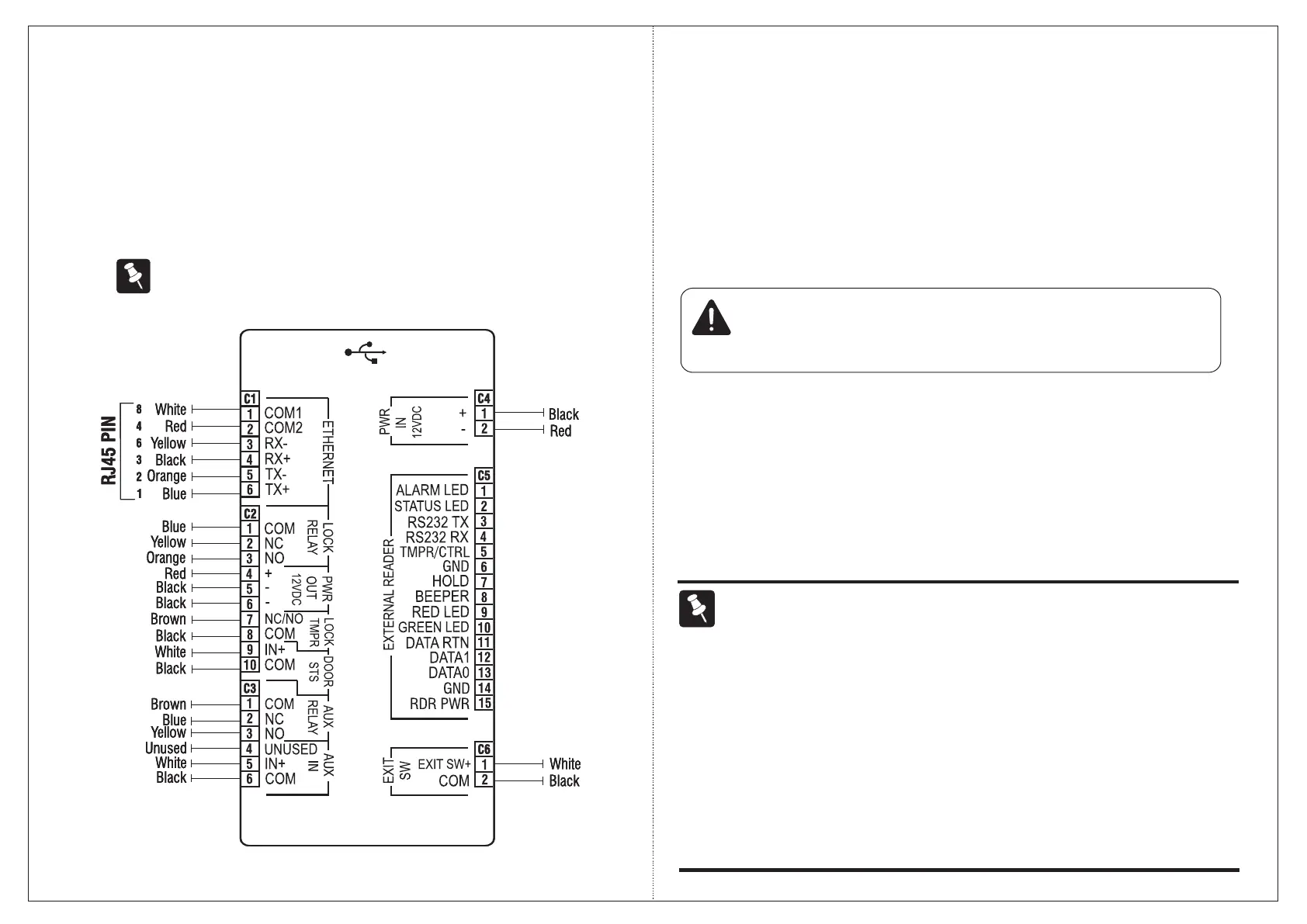
Step 4: Connecting the wires
Ÿ If your wiring is from behind the surface/through an electrical box, first draw out
sufficient length of the cables from rectangular hole you have cut on the
mounting surface.
Ÿ Make the electrical connections.
Ÿ Refer the wire color code mapping for the terminals (figure 4).
The Variant COSEC DOOR FOP has all the connectors shown below
whereas COSEC DOOR FOT has only Power, Ethernet and Exit switch
connectors.
Figure 4
Ethernet
Ÿ Connect the Ethernet cable (with RJ45 plug at one end) into the 'ETHERNET'
terminal (C1).
Door Lock
Ÿ Use the electromagnetic door lock cable (10-pin connector at one end and free
at the other) to connect a Door Lock to the Door Lock terminal (C5).
Door Lock spec: Relay SPDT, Form C, 2A @ 24 VDC
Power
Ÿ Insert the power supply cable (2-pin connector with a DC jack on one end) into
the power terminal 'PWR In (C6)'. Care must be taken to maintain the correct
polarity.
Ÿ Connect the power adapter to the DC jack. Plug the adaptor into a power outlet.
[ ]
If connecting Matrix PSBB-Universal Mains Power Supply (13.8 VDC@2A) with battery backup
to the PWR In terminal, be sure to maintain correct polarity.
CAUTION
Do not apply Power to the unit until you have completed all the connections.
NOTE
Ÿ Always use a standard hydraulic door closer to ensure that the door closes
automatically after an entry or exit. This is to prevent “door open too long” or “door left
open” alarms.
Ÿ The NO or NC output can operate DC-powered locking devices like electro-
mechanical strikes and magnetic locks. The maximum permitted current is 500 mA @
12VDC per output.
Ÿ If you are using a lock of higher capacity, you must use an external 12/24 VDC power
supply, according to the technical specifications of the magnetic lock.