Do you have a question about the Matrix PEL-8000 Series and is the answer not in the manual?
Lists the primary functionalities and capabilities of the PEL-8000 series electronic load.
Presents detailed specifications for PEL-8150 and PEL-8300 models, including power, current, voltage, and modes.
Details the Power-On Self-Test procedure and expected VFD display messages.
Provides troubleshooting steps for issues encountered when the electronic load fails to start.
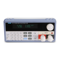
Describes the layout and components of the front and rear panels of the PEL-8000 series.
Explains the function of each key on the electronic load's control panel.
Guides users on how to navigate and operate the electronic load's menu system.
Details the four fundamental operating modes: CC, CV, CR, and CP.
Explains how to operate the electronic load in Constant Current mode.
Details the standard operation within Constant Current mode.
Describes the load and unload functionality in Constant Current mode.
Explains the soft-start feature for Constant Current mode.
Details the mode where CC transfers to CV based on voltage.
Explains how to operate the electronic load in Constant Resistance mode.
Details the standard operation within Constant Resistance mode.
Describes the load and unload functionality in Constant Resistance mode.
Details the mode where CR transfers to CV based on voltage.
Explains how to operate the electronic load in Constant Voltage mode.
Details the standard operation within Constant Voltage mode.
Describes the load and unload functionality in Constant Voltage mode.
Explains the soft-start feature for Constant Voltage mode.
Explains how to operate the electronic load in Constant Power mode.
Details the standard operation within Constant Power mode.
Enables testing dynamic characteristics by switching load currents or voltages.
Describes operation where the load continuously switches between two values.
Details operation where the load switches based on trigger reception.
Explains operation triggered by external signals or events.
Covers setting parameters for dynamic tests like levels, widths, and rise/fall times.
Details how to control output waveforms like square, triangle, and trapezoidal.
Explains how to generate a square wave output.
Explains how to generate a triangle wave output.
Explains how to generate a trapezoidal wave output.
Details methods for activating trigger control in dynamic test modes.
Enables sequential operation by editing and executing data lists.
Guides on editing LIST files, including minimum time unit and output modes.
Explains how to execute pre-defined LIST files.
Allows for automated testing with configurable steps, modes, and parameters.
Details how to create and configure automatic test sequences.
Configures trigger output timing and electrical characteristics for automatic tests.
Guides on initiating and executing automated test sequences.
Manages input status and short-circuit operation modes.
Details the simulation of short circuit on the input.
Explains how to turn the input ON or OFF.
Defines the rated current, voltage, and power range for the electronic load.
Covers various protection features to safeguard the load and DUT.
Details the over-voltage protection mechanism and settings.
Details the overcurrent protection mechanism and settings.
Details the over power protection mechanism and settings.
Describes protection against reversed input polarity.
Details the over temperature protection mechanism.
Enables remote measurement and control of the electronic load.
Guides on performing battery capacity tests using the electronic load.
Details the operation method for conducting battery capacity tests.
Covers the Modbus application protocol for communication with the load.
Provides an overview of the Modbus application protocol structure.
Details how to set the additional address and communication parameters.
Explains the procedure for setting the load's communication address.
Guides on selecting communication parity and verification methods.
Details how to select the communication baud rate.
Describes the data format and byte order used in command frames.
Lists the available function codes for Modbus communication.
Explains the cyclic redundancy check (CRC) for error detection.
Details the structure and parsing of complete communication command frames.
Defines addresses and attributes for coil bits used in communication.
Lists command register values and their corresponding operation descriptions.
Describes common operations like remote control, input, and short circuit.
Highlights safety signs like ground point and high voltage danger.
Details procedures for product repair and service.
Specifies conditions under which the quality guarantee does not apply.
States that manual contents are subject to change without notice.
| Brand | Matrix |
|---|---|
| Model | PEL-8000 Series |
| Category | Fitness Equipment |
| Language | English |