15
ASSEMBLY
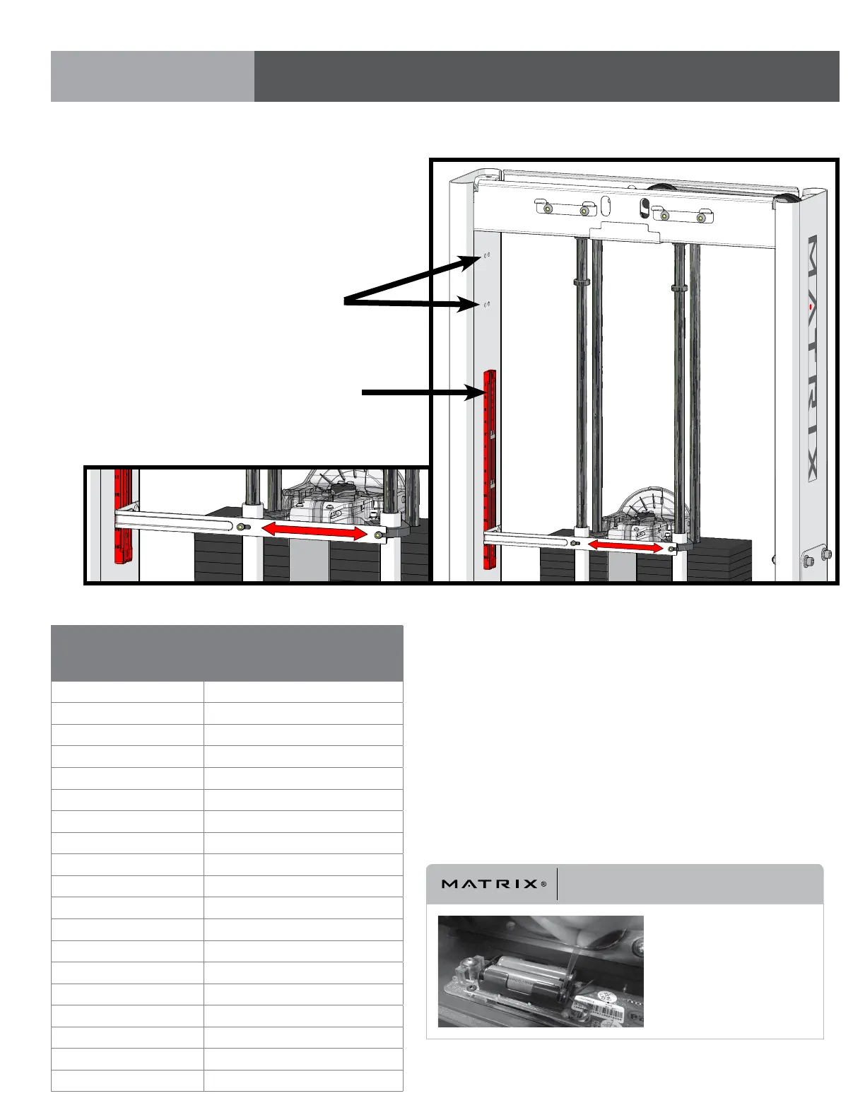
STEP 1 | REP COUNTER LIMIT SWITCH INSTRUCTIONS & NOTES
PART 4: LIMIT SWITCH ASSEMBLY
Assemble (3) sensors located
per machine chart shown below.
Machine
Sensor Locations (Sensor
“A” = Top, “B” = Middle, “C” =
Bottom)
Chest Press A5, B9, C13
Shoulder Press A4, B9, C12
Leg Extension A7, B10, C13
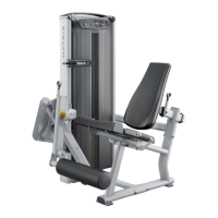
Seated Leg Curl A7, B11, C15
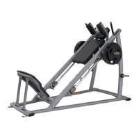
Leg Press A10, B11, C14
Lat Pulldown A2, B6, C12
Triceps Press A5, B9, C12
Seated Row A2, B7, C13
Bicep Curl A11, B12, C15
Hip Abduction A8, B9, C13
Hip Adduction A10, B11, C13
Pec Fly A5, B8, C12
Lateral Raise A7, B8, C15
Abdominal Crunch A10, B11, C13
Back Extension A7, B8, C13
Calf Extension A9, B11, C15
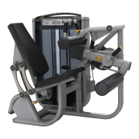
Prone Leg Curl A8, B9, C15
Rotary Torso A11, B12, C15
Glute A6, B11, C15
Route wires in groove
Thread zip ties through
holes to secure cables
If necessary, adjust the proximity of the magnet by sliding magnet holder closer to sensors.
IMPORTANT NOTICE
PLEASE NOTE:
Be sure to remove the insulating
sheet when installing the
Rep Counter.