132 Appendix F: The Matrox Iris GTR breakout board
Push buttons
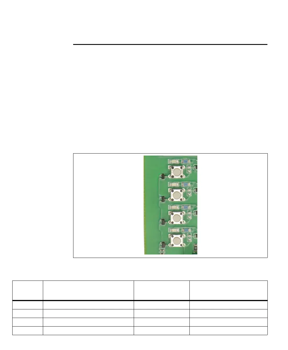
Each push button (SW1, SW4, SW7, and SW9) generates an auxiliary input signal
that is sent to your Matrox Iris GTR through the Matrox Iris GTR
breakout board’s camera connector (J1). When you press a push button to create
an auxiliary input signal, signal bounce (also called chatter) might occur. To
guarantee that the created auxiliary input signal is not interpreted as multiple input
pulses, set the minimum period of time (debounce time) during which any shorter
pulses are considered noise, and are suppressed. The debounce time can be set
using Matrox Design Assistant or MIL.
Each auxiliary input signal should have only one input source. For example, when
a push button is used to provide an auxiliary input signal, it should always be the
only source of input for that signal, and not have to compete with the signal from
a re-routed output signal or a signal from a connected third-party device.
The Matrox Iris GTR breakout board reference for the push buttons is as follows:
Push button Description Matrox Iris GTR
signal received
Routed through the
Matrox Iris GTR breakout board’s
camera connector
Input 6/SW1 Auxiliary signal 6 (input). AUX_OPTOIND_IN6 Gray
Input 5/SW4 Auxiliary signal 5 (input). AUX_OPTOIND_IN5 Black
Input 4/SW7 Auxiliary signal 4 (input). AUX_OPTOIND_IN4 Red
Input 3/SW9 Auxiliary signal 3 (input). AUX(TRIG)_OPTOIND_IN3 Pink