Switches reference 135
Switches reference
Your Matrox Iris GTR breakout board has 6 switches designed to redirect the
signals of your Matrox Iris GTR. Each switch has two states: on and off; each state
is described below.
Each switch is named and listed with its board label.
1
2
3
4
1
2
3
4
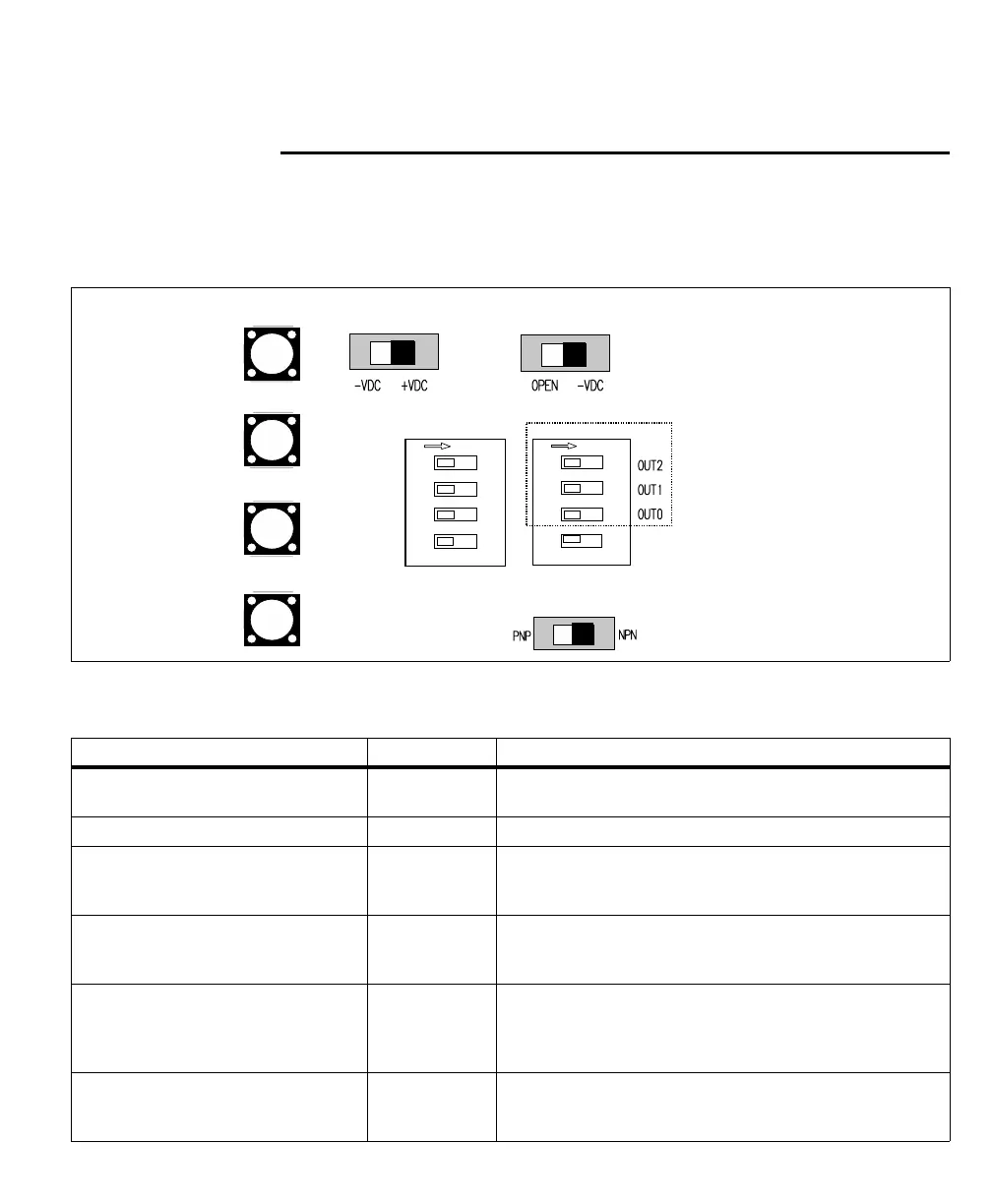
Output-to-input
bypass switches
OFF/ON
Output pullup
resistor switches
OUT2 → IN6
OUT1 → IN5
OUT0 → IN4
OUT0 → IN3
OFF/ON
IN_COM
selector
OUT_COM
selector
Output-to-ICS3 selector
IN_COM TERM
(External/on-board)
Matrox breakout board switch name Board label Description
Output-to-input bypass switches SW5[1] - SW5[4] Redirects a specific auxiliary output signal from your Matrox Iris GTR to
an auxiliary input signal of your Matrox Iris GTR.
Output pullup resistor switches SW6[1] - SW6[3] Applies a pullup of 2.5 KOhms to a specific auxiliary output signal.
IN_COM_TERM switch SW6[4] Specifies whether AUX_OPTOIND_IN_COMMON is connected to an
on-board or an external voltage source/return path for all Matrox Iris GTR
auxiliary input signals.
IN_COM selector switch SW2 Specifies whether your Matrox Iris GTR breakout board will provide a
return path or a voltage source for all Matrox Iris GTR auxiliary input
signals (when the IN_COM_TERM switch is set to ON).
OUT_COM selector switch SW3 Specifies whether the common return path for all Matrox Iris GTR
auxiliary output signals are connected internally through the Matrox
Iris GTR breakout board or externally through the output connector’s
OUT_COM wire-terminal (J6[OUT_COM]).
Output-to-ICS3 selector switch SW8 Specifies whether the NPN or the PNP wire-terminal of the ICS3
connector will carry auxiliary output signal 0 to the connected third-party
lighting controller.