126 Appendix F: The Matrox Iris GTR breakout board
Power source connectors
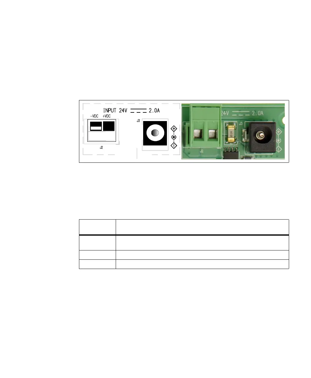
The power source connectors are a combination of two screw-wire-terminals (J2)
and one DC power socket (J3). You can either connect power to the DC power
socket or the two wire-terminals, but not both simultaneously. This connection
powers both the Matrox Iris GTR breakout board and your connected Matrox
Iris GTR smart camera. Note that a DC power supply (compatible with the DC
power socket (J3) is provided in the Matrox Iris GTR starter kit.
❖ Note that the screw-wire-terminals of the power source connector are designed to
receive power from an external source and should not be connected to the
open-ended digital I/O and power cable.
The pinout for the power source connector is as follows:
Board
reference
Description
J3/DC Input External DC input (+VDC). This connection is rated up to 24 V (2 A). Note that this power
socket includes both +VDC (the pin) and -VDC (the shielding).
J2/+VDC External DC input (+VDC) for use with an open-wire power cable, rated up to 24 V (2 A).
J2/-VDC DC voltage reference (-VDC) for use with an open-wire power cable.