Open-wire connectors reference 125
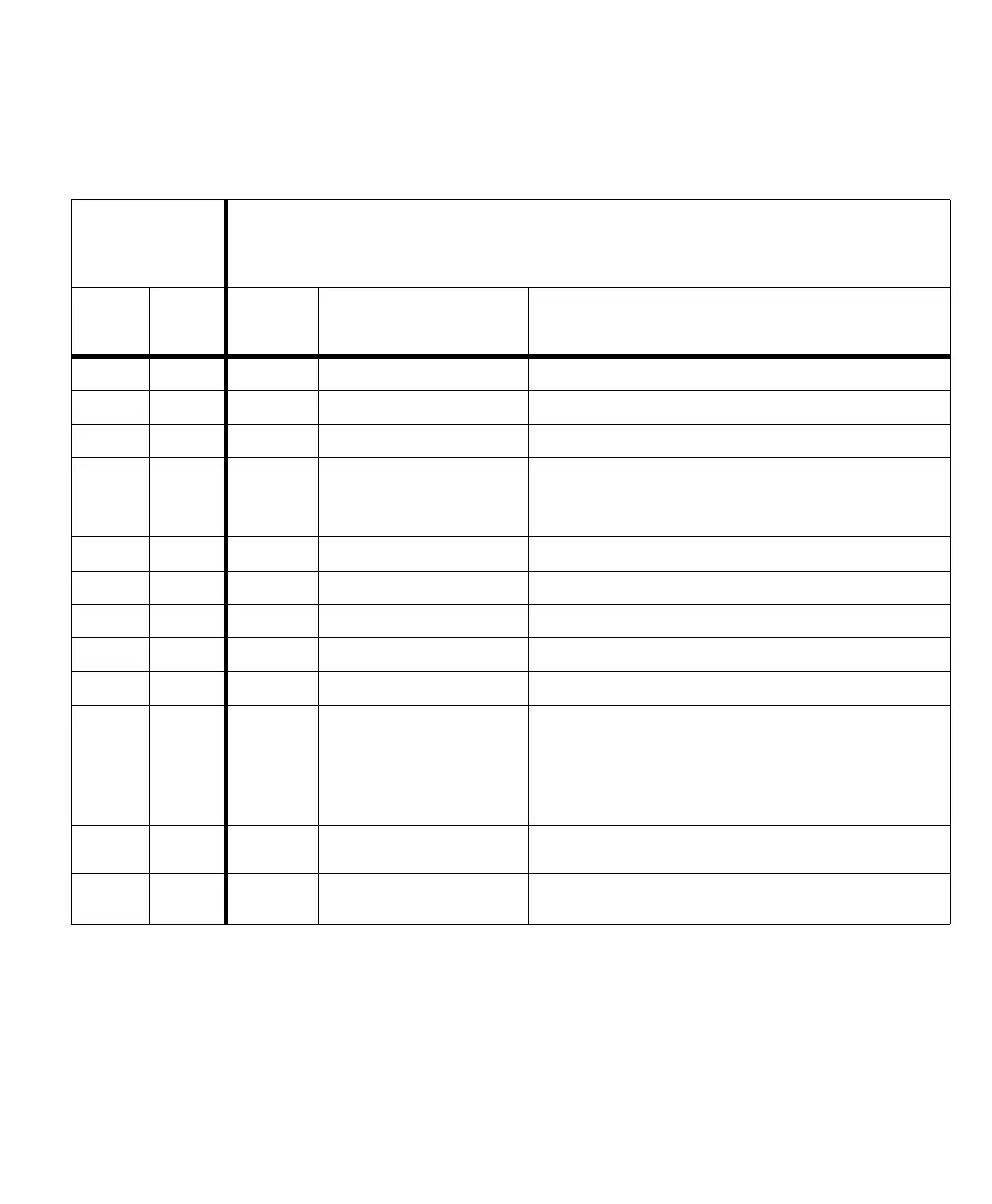
The pinout for the Matrox camera connector (J1) on the Matrox Iris GTR
breakout board is as follows.
Matrox camera
connector on the
Matrox Iris GTR
breakout board
Digital I/O and power connector on Matrox Iris GTR
Wire
color
Wire
-terminal
Matrox
Iris GTR
pin number
Signal name Description
Gray J1[1] 8 AUX_OPTOIND_IN6
Auxiliary signal 6 (input)
a, b
.
Black J1[2] 7 AUX_OPTOIND_IN5
Auxiliary signal 5 (input)
a, b
.
Red J1[3] 9 AUX_OPTOIND_IN4
Auxiliary signal 4 (input)
a, b
.
Pink J1[4] 5 AUX(TRIG)_OPTOIND_IN3
Auxiliary signal 3 (input)
a, b
.
This auxiliary input signal is typically used to trigger the grab, but
the signal can be used for any other purpose.
Yellow J1[5] 6 AUX_OPTOIND_IN_COMMON
Auxiliary signal (input) common
b
.
White J1[6] 3 AUX_OPTOIND_OUT2
Auxiliary signal 2 (output)
b
.
Red-blue J1[7] 12 AUX_OPTOIND_OUT1
Auxiliary signal 1 (output)
b
.
Violet J1[8] 10 AUX_OPTOIND_OUT0
Auxiliary signal 0 (output)
b
.
Brown J1[9] 1 AUX_OPTOIND_OUT_COMMON
Auxiliary signal (output) common
b
.
Blue J1[10] 2 AUX_AREF_OUT7 Analog intensity control signal (output).
Supported function: a voltage-controlled signal designed to be
received by a lighting controller (such as, an Advanced Illumination
inline control system (ICS3),
a
Smart Vision Lights Brick light, or a
similar device).
Gray-pink J1[11] 11 -VDC Negative pin of the power provided to your Matrox Iris GTR from the
Matrox Iris GTR breakout board.
Green J1[12] 4 +VDC Positive pin of the power provided to your Matrox Iris GTR from the
Matrox Iris GTR breakout board.
a. Can be either the positive or negative pin, depending on whether the auxiliary input signals are in sinking or sourcing mode, respectively.
b. Note that the status LEDs on your Matrox Iris GTR breakout board break the electrical isolation provided by the opto-isolated auxiliary signals from your Matrox
Iris GTR.