38 Chapter 4: Matrox Radient eV-CXP hardware reference
User-defined signals
Any auxiliary input or output signal can be configured as a user-defined signal.
User-defined signals are handled with registers that are written to (user outputs)
or read from (user inputs). When an auxiliary input signal is configured as a
user-defined input signal, it is associated with a bit of the user input register. When
required, the register value is read. When an auxiliary output signal is configured
as a user-defined output signal, it is associated with a bit of the user output register.
The value of the user output register is output on that auxiliary output signal.
Once a signal is set as a user-defined signal, your application can interpret this
signal as required.
To control and inquire user-defined signals, use the MIL-Lite functions
MdigControl() and MdigInquire(), respectively, with M_USER_BIT_...
Quadrature decoder
Matrox Radient eV-CXP features four quadrature decoders. They are used to
decode input from a rotary encoder with quadrature output. A rotary encoder is
a device that provides information about the absolute position and direction of a
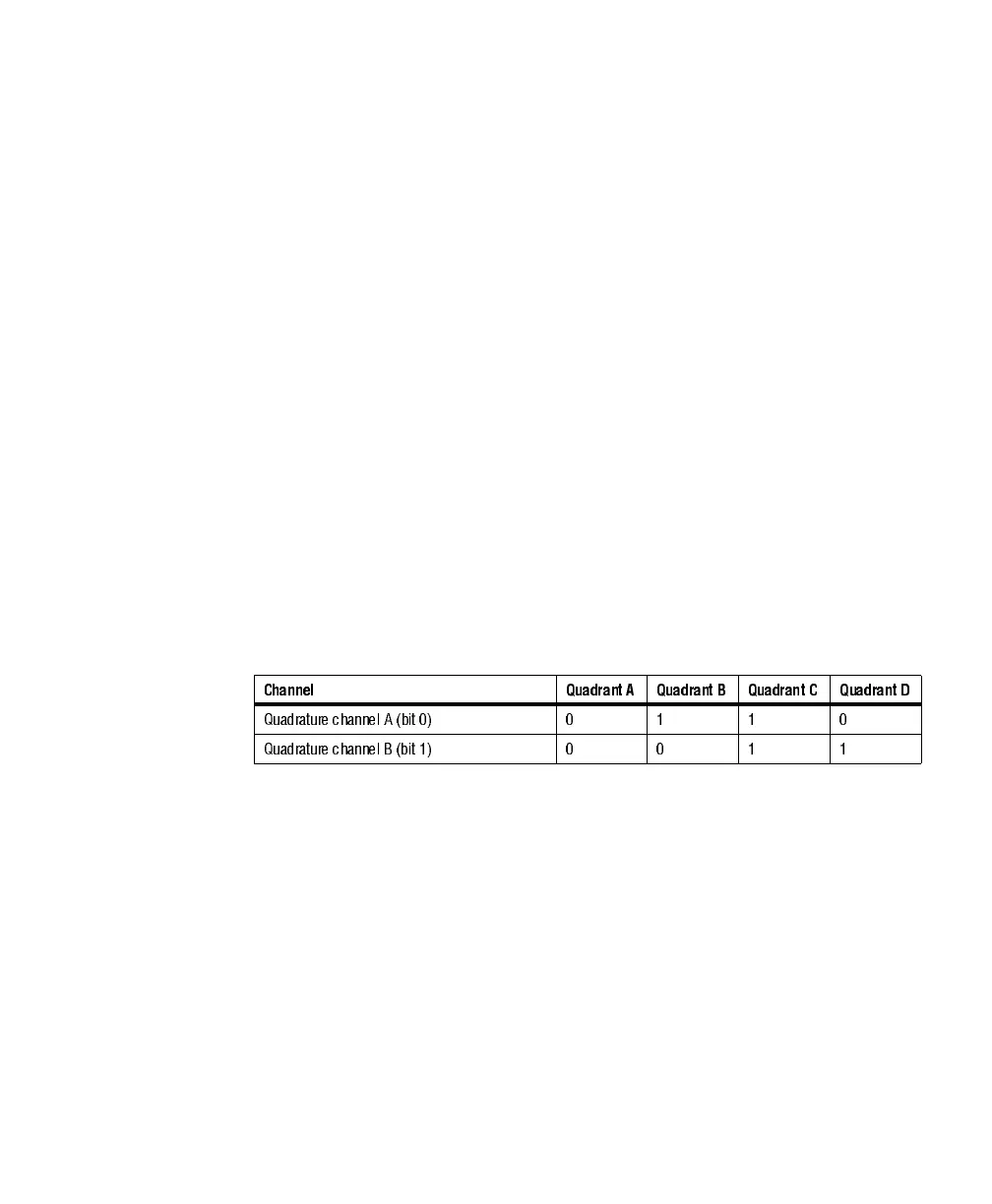
rotating shaft. The encoder outputs a two-bit code (also known as Gray code) on
two pairs of LVDS wires in a precise sequence, as shown in the table below.
From this sequence, the position of the rotating shaft and the direction of rotation
can be determined.
The quadrature decoder can decode Gray code and update a 32-bit internal
counter. The sequence going from Quadrant A through Quadrant B through
Quadrant C through Quadrant D increments the 32-bit internal counter. You can
read the counter at different stages of the grab or trigger a grab based on the value
of the counter. The quadrature decoder supports encoder frequencies of up to 50
MHz.
Channel Quadrant A Quadrant B Quadrant C Quadrant D
Quadrature channel A (bit 0) 0 1 1 0
Quadrature channel B (bit 1) 0 0 1 1