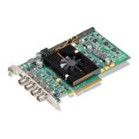
Connectors on the Matrox Radient eV-CXP board 57
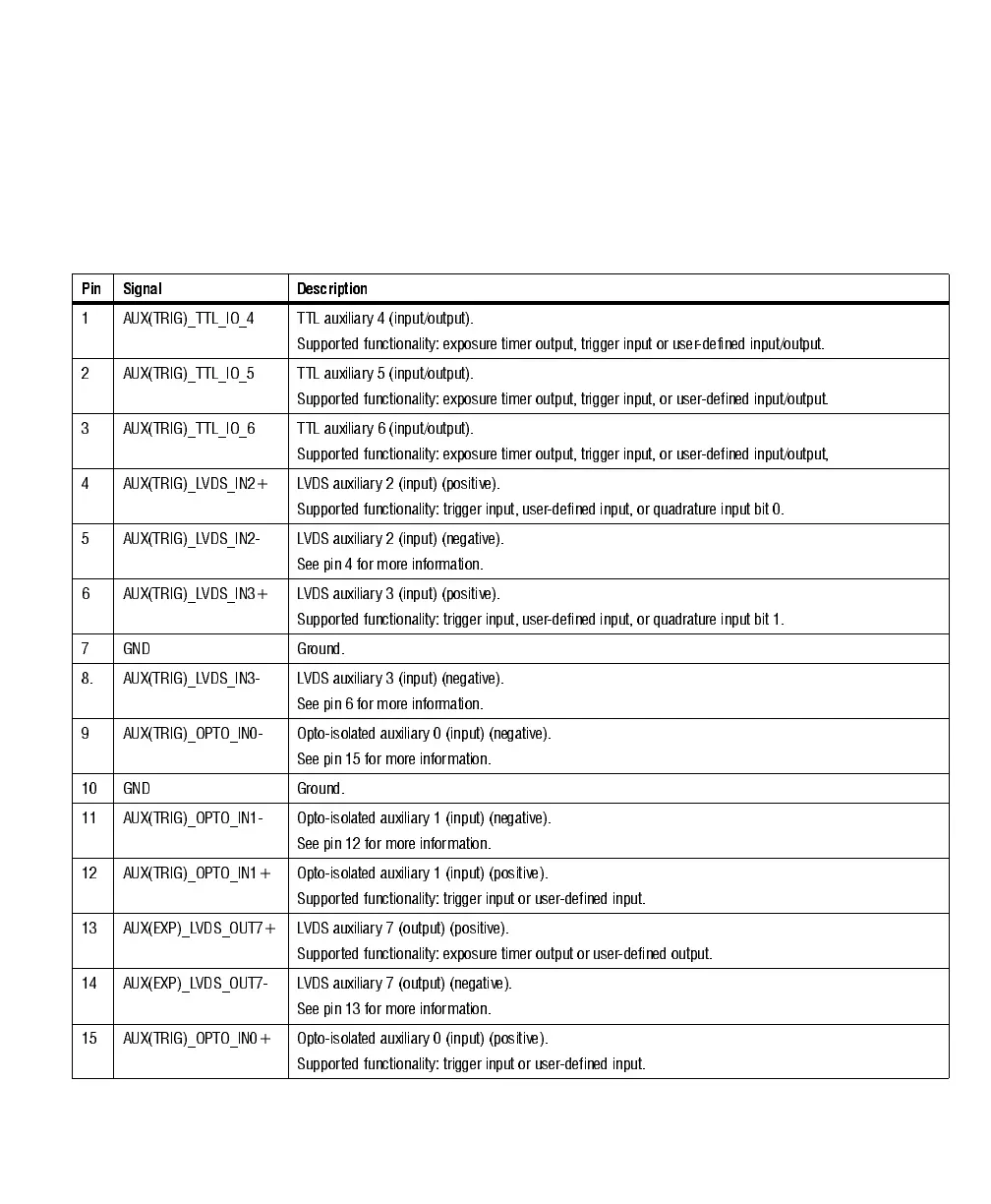
The pinout for auxiliary I/O connector 0 is as follows. Auxiliary I/O connectors
1, 2, and 3 have the same pinout as auxiliary I/O connector 0, except you must
add 8, 16, or 24, respectively, to their signal numbers. For example,
AUX(TRIG)_TTL_IO_4 (TTL auxiliary 4) on connector 0 would be
AUX(TRIG)_TTL_IO_12 (TTL auxiliary 12) on connector 1.
Pin Signal Description
1 AUX(TRIG)_TTL_IO_4 TTL auxiliary 4 (input/output).
Supported functionality: exposure timer output, trigger input or user-defined input/output.
2 AUX(TRIG)_TTL_IO_5 TTL auxiliary 5 (input/output).
Supported functionality: exposure timer output, trigger input, or user-defined input/output.
3 AUX(TRIG)_TTL_IO_6 TTL auxiliary 6 (input/output).
Supported functionality: exposure timer output, trigger input, or user-defined input/output,
4 AUX(TRIG)_LVDS_IN2+ LVDS auxiliary 2 (input) (positive).
Supported functionality: trigger input, user-defined input, or quadrature input bit 0.
5 AUX(TRIG)_LVDS_IN2- LVDS auxiliary 2 (input) (negative).
See pin 4 for more information.
6 AUX(TRIG)_LVDS_IN3+ LVDS auxiliary 3 (input) (positive).
Supported functionality: trigger input, user-defined input, or quadrature input bit 1.
7 GND Ground.
8. AUX(TRIG)_LVDS_IN3- LVDS auxiliary 3 (input) (negative).
See pin 6 for more information.
9 AUX(TRIG)_OPTO_IN0- Opto-isolated auxiliary 0 (input) (negative).
See pin 15 for more information.
10 GND Ground.
11 AUX(TRIG)_OPTO_IN1- Opto-isolated auxiliary 1 (input) (negative).
See pin 12 for more information.
12 AUX(TRIG)_OPTO_IN1+ Opto-isolated auxiliary 1 (input) (positive).
Supported functionality: trigger input or user-defined input.
13 AUX(EXP)_LVDS_OUT7+ LVDS auxiliary 7 (output) (positive).
Supported functionality: exposure timer output or user-defined output.
14 AUX(EXP)_LVDS_OUT7- LVDS auxiliary 7 (output) (negative).
See pin 13 for more information.
15 AUX(TRIG)_OPTO_IN0+ Opto-isolated auxiliary 0 (input) (positive).
Supported functionality: trigger input or user-defined input.