devices. If you connect two devices, you must configure one device
as Master, and one device as Slave. See the documentation
provided with the devices for information on this. To install more
drives, use another IDE cable and connect one or two devices to
IDE2.
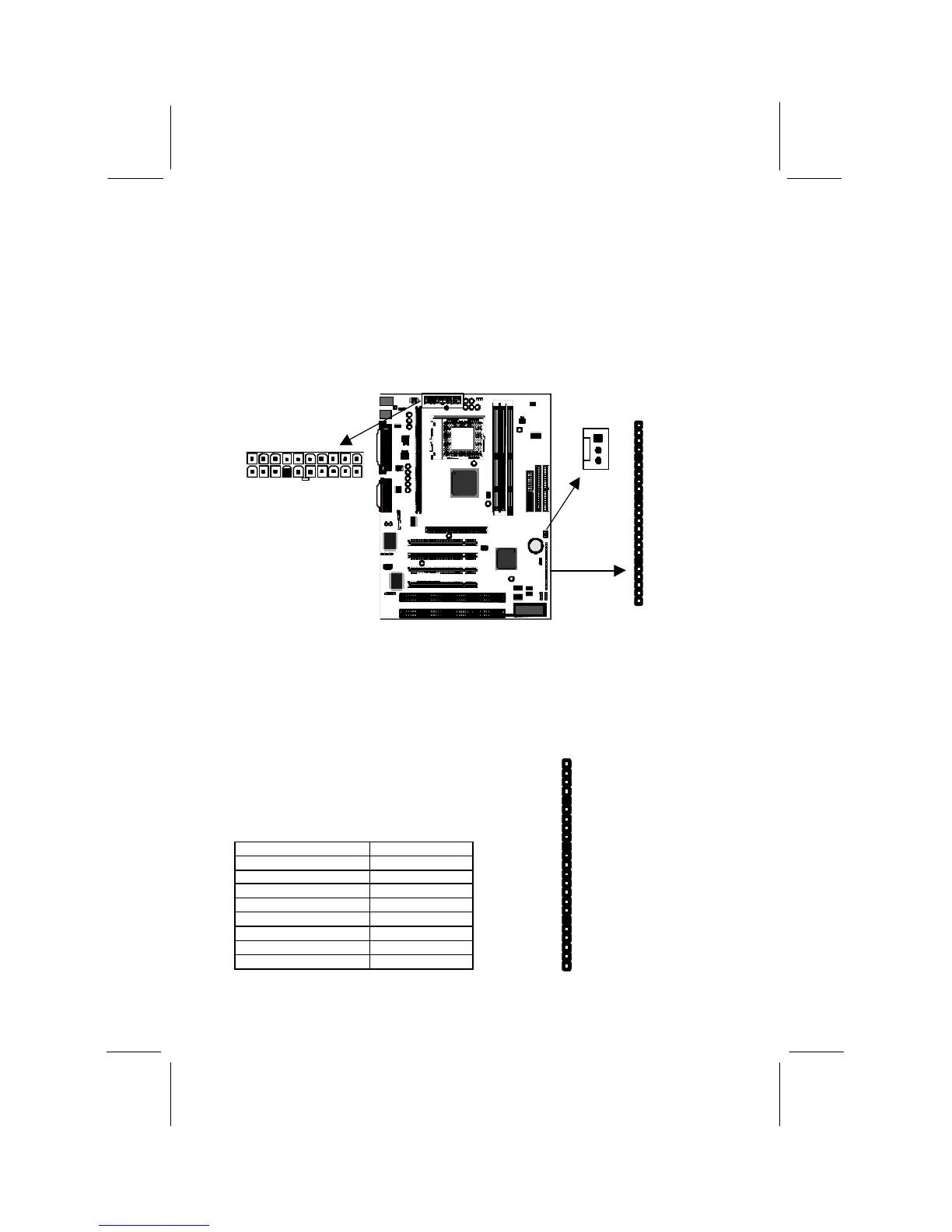
Power Connector, Panel Connector & Case Fan
1. Locate the power connector ATX1. Connect the power cable from
the power supply unit to ATX1. The connector is keyed so that it can
only be installed correctly.
2. If your system case has a built-in cooling fan, you can supply power
to the fan from the case fan power connector CASEFAN1. Connect
the power cable from the fan to CASEFAN1.
3. Locate the bank of switch and indicator
connectors PANEL. These connectors
provide control functions to your system
case. Use the illustration on the right and
the table below to make the connections.
Function Pins
Power Indicator 1+, 2+, 3
Sleep Switch 4, 5
Green Indicator 7+, 8+, 9
Keylock 10, 11
Reset Switch 12, 13
Speaker 15+, 16, 17, 18
Hard Disk Indicator 20+, 21
Power Switch 22+, 23
PANEL
CASEFAN1
ATX1
 Loading...