5
Mechanical
Transmitters are installed on the meter at the factory. If a transmitter needs to be replaced in the
field, use the following procedure:
1. Disconnect wiring and remove the two socket cap screws to remove old transmitter.
2. Align rounded alignment key on new transmitter with corresponding notch on flow meter and
drop into place.
3. Tighten both socket cap screws until snug. Ensure that the transmitter is not crooked, then turn
screws a 1/4 turn. Do not over tighten.
Electrical
This model is wired at the factory. All that is required is to connect the 4-pin Connector mating cable
into the remainder of the system as follows:
Frequency Output Blue: Case Ground Black: Common Brown: Power (+5 to 26 Vdc) White: Output Signal
Analog Output Blue: Case Ground Black: Common Brown: 12 or 24 Vdc (see housing)
Grey: Output Signal + White: Output Signal —
High Temperature Operation above 65°C (150°F)
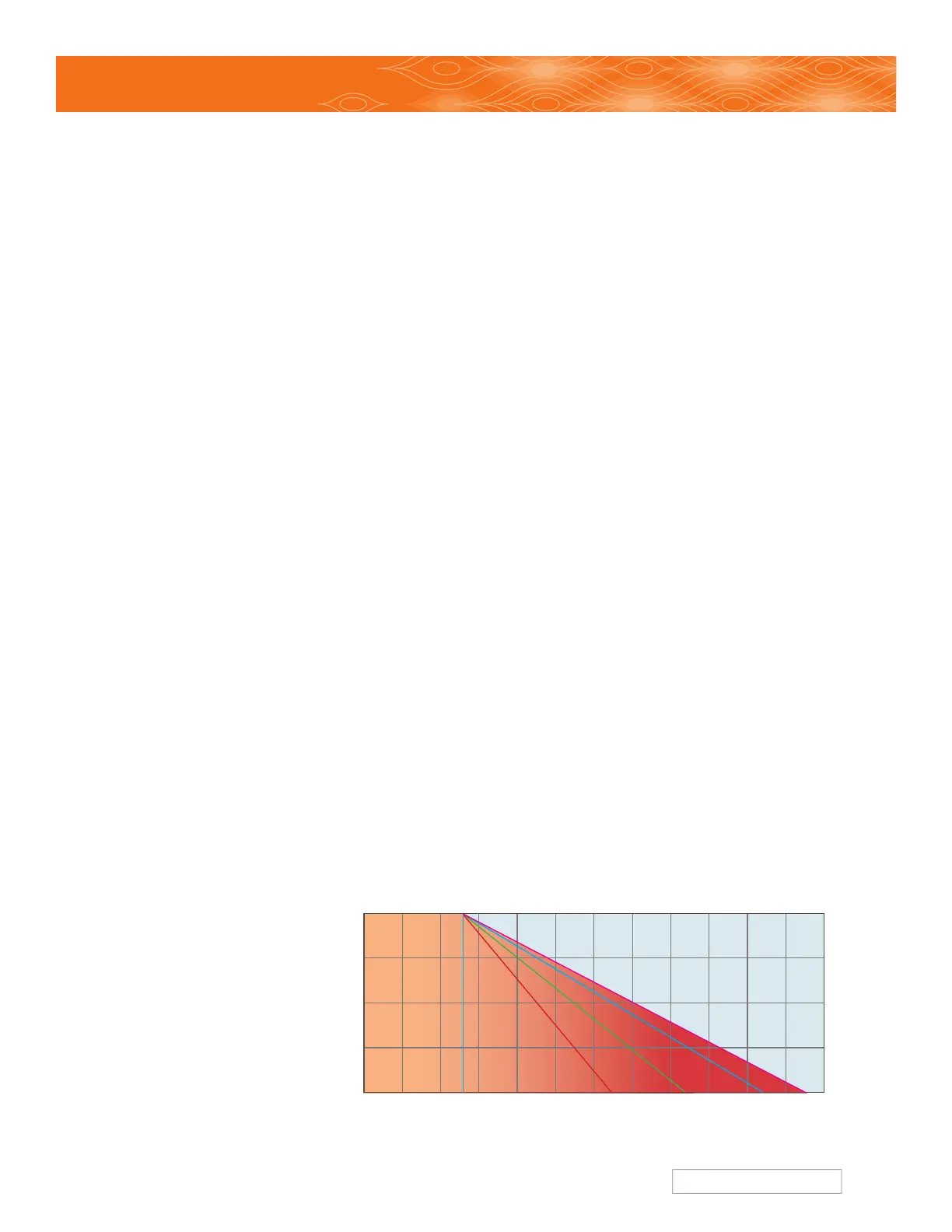
The operating limit of the meter/transmitter is a function of both the ambient and the metered fluid
temperature, as shown in the graph below. Although the electronic components are rated to 80°C
(175°F), additional heat can be conducted from the flow meter into the transmitter housing requiring
a lower ambient temperature limit for high fluid temperatures.
To prolong the life of the transmitter and reduce the risk of component related failures over time,
high ambient temperatures >65°C (150°F) should be avoided if possible. It is a good idea to locate
the transmitter away from hot spots such as steam pipes, ovens and heaters. When working with
elevated fluid temperatures >65°C (150°F), insulating the flow meter is recommended to reduce the
risk of burns, and to reduce the heating of the electronics by convection of hot air off of the meter
(especially for larger meters).
The upper temperature
limits shown in the curves
rely on ambient convection
to remove heat from the
transmitter housing, cooling
the electronics. For this
reason, if operating near
the upper temperature
limit, the transmitter should
not be insulated. At these
elevated temperatures, the
transmitter will be
very hot – exercise
appropriate caution.
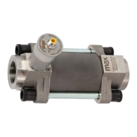
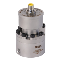
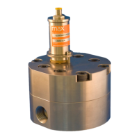
Installation -Transmitter
0 50
80
170 210
280265
20
40
60
80° C
100 150 200 250
300° C
Temperature Limits
Model 269 Transmitter Series
Process Temperature °C
Standard
model limit
Hi temp 24vdc
model limit
Ultra Hi*
model 5vdc
operation
Ultra Hi*
model 24vdc
operation
Hi temp 5vdc
model limit
Ambient Temperature °C
*Note: Ultra high temp model must be mounted
with transmitter on side of the flow meter
 Loading...