EasyManua.ls Logo

Max P Series User Manual

Max P Series
38 pages
To Next Page IconTo Next Page
Page #1 background imageLoading...
Page #1 background image
P-Series User Manual
P001HS
P001LA
P002
P213
P214
P215
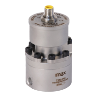
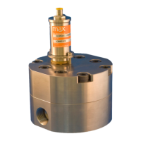
Positive Displacement Piston Flow Meters

Questions and Answers:

Max P Series Specifications

General IconGeneral
BrandMax
ModelP Series
CategoryMeasuring Instruments
LanguageEnglish

Summary

Safety and Precautions

Operational Hazards

Critical warnings about operating the flow meter to prevent damage or injury.

Installation and Operation Best Practices

Essential steps for safe and effective installation and operation of the flow meter.

How It Works

Installation - Mechanical

Fitting Installation

Guidance on installing various types of fittings for proper meter connection.

System Plumbing and Support

Recommendations for system setup, filtration, cleaning, and thermal management.

Mechanical - Operation

Installation - Electrical

Electrical Connection Overview

General safety, warnings, and overview of electrical components and wiring.

Quick Start and Configuration

Initial setup steps and required adjustments for flow meter output settings.

Electrical Installation Instructions - 5-pin Turck Connectors

Frequency Output Wiring

Pinout and wiring details for frequency output transmitters.

Analog Output Wiring

Pinout and wiring details for analog output transmitters.

Current Sinking Wiring

Wiring instructions for current sinking output transmitters.

Electrical - Operating Information

High Temperature Instructions

Troubleshooting Indicators

Explains LED indicators for normal operation and error conditions.

Field Compensation of Transmitter

Compensation Process and Settings

Details on transmitter LED functions, compensation algorithm, and accessing settings.

Flow Rate Compensation Table

Table specifying minimum and maximum flow rates for field compensation.

LED Functions

Specifications

P001LA Specifications

Detailed specifications for the P001LA flow meter model.

P001 Specifications

Detailed specifications for the P001 flow meter model.

P002 Specifications

Detailed specifications for the P002 flow meter model.

P213 Specifications

Detailed specifications for the P213 flow meter model.

P214 Specifications

Detailed specifications for the P214 flow meter model.

P215 Specifications

Detailed specifications for the P215 flow meter model.

Dimensions

P001LA Dimensions

Dimensional drawings and measurements for the P001LA flow meter.

P001 Dimensions

Dimensional drawings and measurements for the P001 flow meter.

P002 Dimensions

Dimensional drawings and measurements for the P002 flow meter.

P213 Dimensions

Dimensional drawings and measurements for the P213 flow meter.

P214 Dimensions

Dimensional drawings and measurements for the P214 flow meter.

P215 Dimensions

Dimensional drawings and measurements for the P215 flow meter.

Charts

Pressure Drop Charts

Graphs illustrating pressure drop versus flow rate for various viscosities.

Flow Meter Configuration and Part Numbering

P001LA Configuration

Guide to configuring the P001LA model and understanding its part numbering.

P213, P214, P215 Configuration

Guide to configuring P213, P214, P215 models and understanding their part numbering.

P001, P002 Configuration

Guide to configuring P001, P002 models and understanding their part numbering.

Available Accessories

Interface Software Kit

USB transmitter programming software and serial cable for adjustments.

Cables

Available cable options for connecting the flow meter transmitter.

Indicators and Totalizers

Panel mount indicator for rate and total display.

Filters and Filter Kits

Inline filters and replacement filter elements for flow meter protection.

PCA Replacement Kits

Replacement kits for the Printed Circuit Assembly (PCA) of the transmitter.

Troubleshooting and Service Request

Troubleshooting Common Issues

Problem and corrective action table for common flow meter issues.

Additional Information Resources

Related product manuals