Do you have a question about the Max H Series and is the answer not in the manual?
Explains how helical rotors ensure high accuracy measurements and outputs.
Details preferred orientations for purging air and minimizing heat transfer.
Guides on using pipe sealant and supporting meter during NPT installation.
Details the procedure to prevent thermal shock for fluids above 82°C.
Discusses wiring considerations and various transmitter component options.
Provides detailed wiring diagrams for frequency and analog output transmitters.
Covers procedures for transmitter removal and maintaining moisture seal integrity.
Explains LED functions for normal operation and error indication.
Describes the compensation algorithm and how to access the PCA button or software.
Details LED indications for normal operation and meter malfunctions.
Explains LED behavior during compensation success or failure.
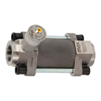
Details flow range, pressure, construction, and transmitter options for H241.
Side and end view dimensions for the H241LS model.
Illustrates pressure drop versus flow rate for various viscosities for the H241.
Illustrates pressure drop versus flow rate for various viscosities for the H242.
Lists interface software, cables, and rate indicator/totalizer accessories.
Provides solutions for common issues like no flow, no indication, or incorrect readings.
| Brand | Max |
|---|---|
| Model | H Series |
| Category | Measuring Instruments |
| Language | English |