P-Series User Manual Rev2022 9
LED Rotation/Output Indicators
All Max transmitters incorporate an alternating red/green or blue/green LED to indicate magnet rotation in the meter.
The color changes each 1/2 revolution of the meter. Additionally, when no ow signal is present, a rapidly ashing red
light indicates the following errors:
Frequency (PN ending N/- or S/-): Flashes 8x per second indicate magnet is not detected
Analog (PN ending A/-, B/-, C/-, D/-):
Flashes 2x per second indicate excessive temperature
Flashes 8x per second indicate magnet is not detected
Flashes 16x per second indicate a wiring fault in the output circuit
Note: There are no selections or adjustments on the circuit board. Setting changes are made through the Interface
Software Kit (SFT-KIT-001), sold separately. If the PCA is not functioning, PCA replacement kits are available by
contacting Max Machinery.
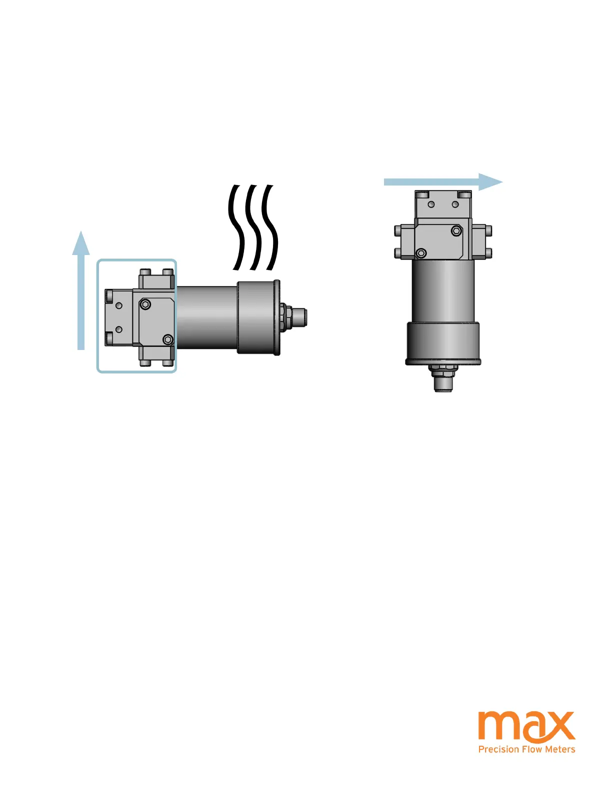
High Temperature Instructions
Troubleshooting
Orient your meter so the transmitter is to the side or below to minimize heat transfer by convection from the ow
meter to the transmitter. The transmitter is the most heat sensitive element in the system. Consult your user manual for
specic limits on uid and ambient maximum temperatures. When operating in the upper temperature ranges, always
insulate the meter but leave the transmitter housing exposed so it radiates heat. An optional heater block can be used
on the ow meter to keep it at the uid operating temperature. For substances solid at room temperature, a heater
block may be required to keep material molten to ow through the meter.
FLOW
FLOW
INSULATION HERE
RADIATE HEAT HERE