P-Series User Manual Rev2022 5
Max P-Series Precision Flow Meters transmitters come from the factory pre-assembled to the mechanical metering
component and congured to be used out of the box based on your submitted application data. Plumb it, wire it, and use
it. The following section describes how to properly wire your Max Flow Meter into your application electronics.
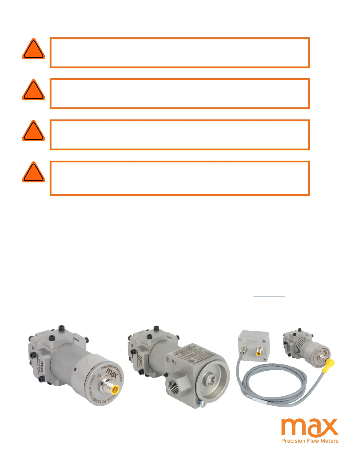
There are various combinations of transmitter components and outputs. These options include:
- Industrial or Hazardous Location Transmitter Housing
- Frequency or Analog Output Signal
- Uni-directional or Bi-directional Output Signal
- Standard, High Temperature, and Ultra High Temperature Housings
To determine what transmitter type you have, refer to the Max Part Number matrices on pages 31-33 and decode your
ow meter part number.
Installation - Electrical
WARNING: Refer to the EXInstall Sheet for proper installation in hazardous
locations.
!
WARNING: Electrical shock hazard. Serious or fatal injury may occur.
Installation/Removal should only be completed by trained and authorized
personnel.
!
!
CAUTION: Verify transmitter output type (Analog or Frequency) before wiring.
Inappropriate wiring could result in damaging the circuit.
CAUTION: Before opening/accessing the electronics lid, make sure the top of
the meter and surrounding components are dry and no moisture or uids can
contact the electrical components. Non-warranty damage may occur.
!