P-Series User Manual Rev2022 2
Your Max Flow Meter has been congured at the factory to be used out of the box based on your submitted application
data. Plumb it, wire it, and use it. The following section will provide instructions on how to properly plumb your Max Flow
Meter in the liquid lines of your application.
Use the “IN” port or follow the ow direction arrow markings for the primary ow direction. Install the meter on the
discharge side of the pump whenever possible. Excessive vibration at the meter should be avoided.
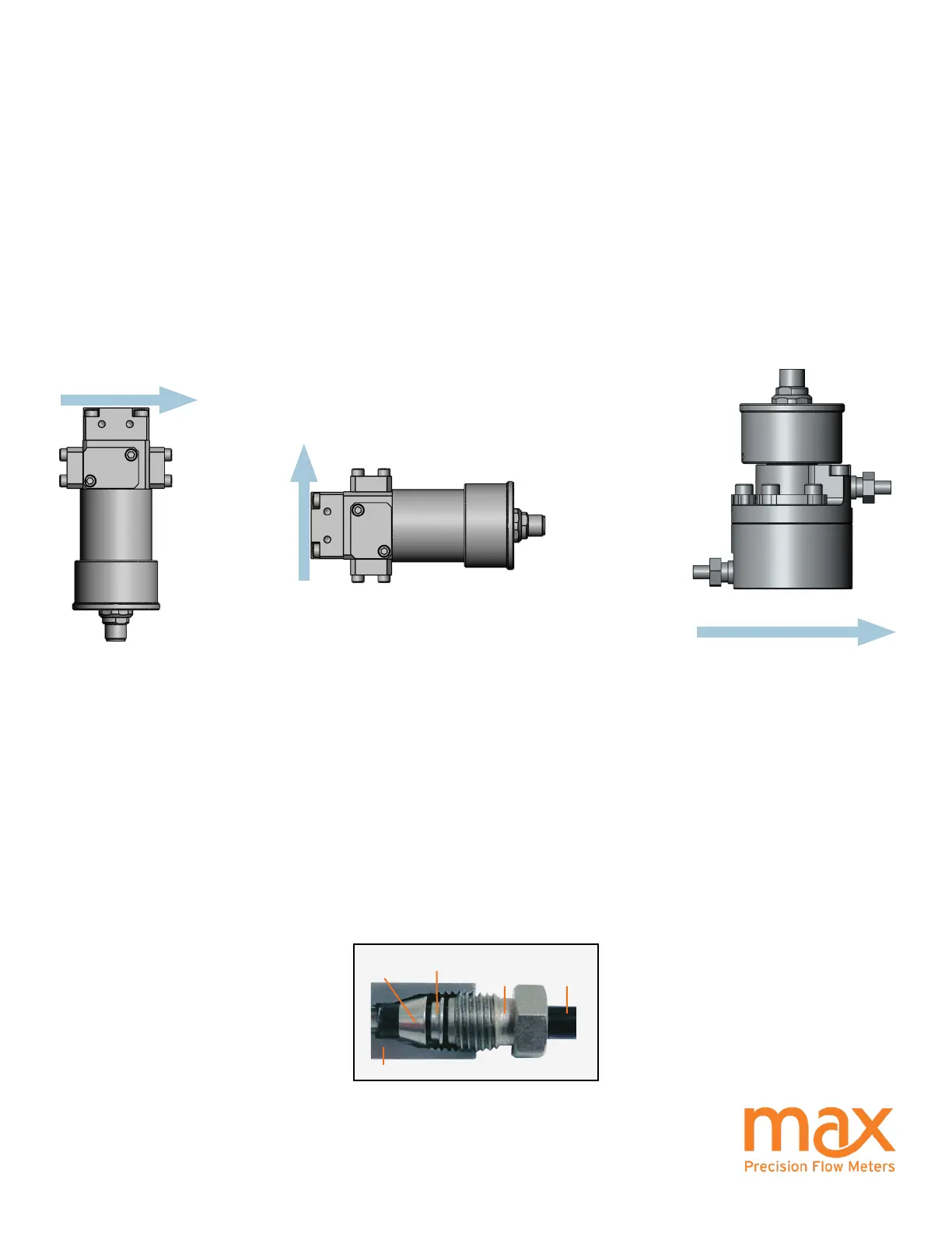
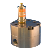
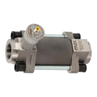
Orientation: Preferred mounting orientation of the meter depends on meter type. The orientation optimizes air purging
and/or minimizes heat transfer to the electronics. P-Series meters with in line ports prefereably mount with the
transmitter facing down or alternately on the side. P001 and P002 with offset ports mount with the transmitter facing
up. These mounting orientations prevent air in the system that can cause response delays and errors in measurement.
NPT ttings: Always use pipe sealant or pipe tape to install ttings, and leave the rst thread of pipe exposed. Ensure
the tape or sealant does not accidentally enter the meter.
SAE / BSPP ttings: Always use process uid compatible lubricant on the o-ring to attach the tting to the meter.
Compression Fittings: P001 compression ttings are based on Swagelok style ferrules (see g. 1). Do not use other
manufacturer’s parts because the sealing angle may not be the same. Fitting kits contain detailed instructions and
are shipped with every meter (contact Max Machinery for spare ferrule kits). Always torque to values on tting kit
instructions. Select tubing grades that meet or exceed your system pressure requirements. If using exible tubing,
install a tubing insert to allow compression ferrules to seal (suggested inserts: Swagelok SS-405-2, SS-405-03 or SS-
405-170). To reuse a tube tting, mark the nut and meter before removal. When re-installing, tighten to align the marks
then tighten a quarter turn farther.
Installation - Mechanical
P001
FLOW
FLOW
P213
Ferrule
Meter body
Lock ring
Nut Fluid line
Figure 2. Compression Fitting
FLOW
P213