Do you have a question about the MAXA i-HPV5H 0140 and is the answer not in the manual?
Instructions on how to store and maintain the manual for future reference and updates.
Explanation of symbols used in the manual to indicate warnings and important information.
Lists forbidden operations and critical safety precautions for safe unit operation and maintenance.
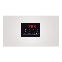
Details on the unit's display screen and the functions of the control panel keys.
Explanation of the status indicated by various LED lights on the control panel for modes and operations.
Configuration of various temperature setpoints for heating, cooling, and sanitary modes.
Access control for different privilege levels requiring password entry.
Functionality to view active alarms and their status on the unit.
Reading temperature and pressure sensor values via the installer menu.
Status check of digital inputs for unit control and configuration.
Modification of main unit parameters, organized by functional groups.
Display and reset of compressor and circulator operating hours.
Access to the alarm log history for troubleshooting and diagnostics.
Viewing current firmware version, revision, and sub-revision.
Functions for firmware and parameter updates via USB connection.
Configuring the circulator for continuous operation, including standby delay settings.
Circulator and compressor activation based on temperature controller signals.
Setting periodic activation intervals and times for the circulator.
Activating the circulator when integration resistors are active.
Managing circulator operation, antifreeze protection, and speed modulation.
Details on compressor control logic for cooling operation.
Details on compressor control logic for heating operation.
How the unit memorizes probe readings during heating and DHW cycles.
Using DHW storage tank for system heating and integration resistor.
Remote activation and deactivation of the unit using a digital input.
Remote selection of operating mode (heating/cooling) via digital input.
Activating DHW production using a digital input as an alternative.
Managing silent ventilation through digital input configuration.
Connecting and configuring system integration resistors for heating support.
Activating and configuring sanitary integration resistors for DHW support.
Using DHW resistance as a single integration resistor for system and DHW.
Setting priorities for system and DHW integration resistor activation.
Managing circulator operation when integration resistors are active.
Enabling a boiler as an alternative or supplement to sanitary resistance.
Synergy of compressor with auxiliary heaters in winter/DHW mode.
Auxiliary heaters enabled with heat pump in heating/DHW mode.
Auxiliary devices operate in place of the heat pump compressor.
Lists possible configurations for integration parameters across operating modes.
Alarm triggered by lack of water flow, with specific conditions and reset.
Alarm activated when water delivery probe exceeds a high-temperature threshold.
Alarm triggered when outlet water probe falls below a set threshold.
Alarms related to probe short-circuit, interruption, or exceeding limits.
Alarms indicating faulty or disconnected pressure transducers.
Covers inverter timeouts, compressor driver issues, and related operational alarms.
Alarms for high and low pressure conditions detected by system transducers.
Includes driver limitations, 4-way valve, lack of voltage, and other system status alarms.
Summary table of various alarm codes and their affected blocks.