Do you have a question about the MAXA i-HPV5H 0270 and is the answer not in the manual?
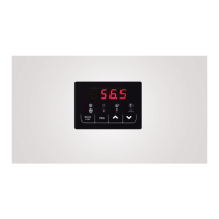
Details the function of each key (MODE, ESC, PRG, UP, DOWN) on the controller interface.
Explains the meaning of different status LEDs (Cooling, Heating, Pump, Alarm, etc.) on the controller.
Details adjustable setpoints for cooling, heating, and sanitary modes with defaults and ranges.
Details how to read sensor values for temperature and pressure.
Enables modification of the unit's main operating parameters.
Provides access to functions related to USB connectivity for updates.
Explains circulator operation based on temperature controller signals.
Details the compressor on/off logic for cooling operations.
Explains the compressor on/off logic for heating operations.
Details heating mode operation when using a DHW storage tank.
Describes the remote ON/OFF function via digital input.
Explains integration logic for heaters/boilers in joint operation or substitution.
Details the alarm triggered by the water-side flow switch.
Covers alarms for faulty or out-of-range probe/pressostat readings.
Covers various alarms related to the compressor driver and inverter.
Details the alarm for detecting excessively high system pressure.
Explains the alarm for detecting excessively low system pressure.