Do you have a question about the MAXA i-290 0106 and is the answer not in the manual?
Instructions on proper storage and accessibility of the manual for optimal use.
Explanation of visual indicators used within the manual for safety and information.
Guidelines for protecting personnel during operation and maintenance activities.
Specifies required safety gear for operators and maintenance personnel.
Identifies mandatory safety signs to be observed on the unit.
Details essential safety information displayed via labels on the unit.
Provides comprehensive safety information for the R290 refrigerant.
Highlights specific hazards and precautions related to R290 refrigerant.
Outlines procedures for vacuuming and charging refrigerant systems with R290.
Procedures for safe and compliant disposal of R290 refrigerant.
Safety guidelines for transporting and storing units containing R290.
General guidelines and precautions for unit installation.
Specifies acceptable temperature ranges for unit transport and storage.
Procedures and safety measures for lifting and handling the unit.
Details the approved methods for lifting the unit using various equipment.
Guidelines for unit placement and required clearances for safe operation.
Defines hazardous areas around the unit due to refrigerant gas.
Specifies danger and safety zones for units installed in open fields.
Defines zones for units installed against a wall.
Specifies zones for units installed in corner locations.
Safety zone considerations for units installed on flat roofs.
Guidelines for safe zone management when installing multiple units side-by-side.
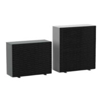
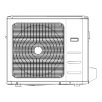
Provides overall dimensional information for the unit series.
Details dimensional specifications for models 0106 and 0109.
Details dimensional specifications for models 0112, 0115, and 0118.
Identifies center of gravity and vibration damper placement.
Guides on how to access the unit's internal components.
Instructions for accessing internal components of specific unit models.
Procedures for accessing internal components of other unit models.
Locates and explains access to thermostat and temperature probes.
Detailed steps for charging the machine's refrigerant circuit.
Guidelines for making hydraulic connections to the unit.
Defines acceptable water quality parameters for the system.
Illustrates standard plumbing configurations for the unit.
Reference to additional technical documentation for installation configurations.
Details the system for draining condensate from the unit.
Instructions for filling and pressurizing the system.
Procedures for draining the unit's system.
Explains the function and installation of the deaerator component.
Presents schematic diagrams of the unit's operational flow.
Presents the functional diagram for specific unit models.
Shows the functional diagram for other unit models.
Guidance on making safe and compliant electrical connections.
Guides on how to access the unit's electrical panel and user board.
Details on connecting the unit's power supply safely and correctly.
Requirements for electrical protection devices like fuses and switches.
Information on the user board connections and terminals.
Information and installation procedures for the external G13 module.
Technical specifications and dimensions of the external G13 module.
Electrical and operational data for the external G13 module.
Instructions for installing the external G13 module.
Reference to control logic documentation for the G13 module.
Information on fuse types and characteristics for the unit.
Procedures for powering on and initiating the unit's operation.
Detailed steps for cleaning the unit's finned coil.
Specific cleaning advice for anti-corrosion treated coils.
Procedures for cleaning the unit's outer casing.
Outlines procedures for non-routine maintenance tasks.
Comprehensive technical specifications for the unit.
Auxiliary electrical specifications and unit power supply details.
Defines minimum and maximum water flow rates for evaporator operation.
Specifies operating limits for cooling water production.
Defines operating limits for heating water production.
Summarizes ambient temperature limits for different operating modes.
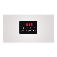
Introduction to the i-CR remote control unit and its functions.
Technical specifications for the i-CR remote control.
Instructions for installing the i-CR remote control on a wall.
Details on connecting the i-CR remote control to the unit.
Explains the functions of the i-CR remote control's keys.
Explains the icons and meanings displayed on the i-CR interface.