Do you have a question about the MAXA i-MAX 0466 and is the answer not in the manual?
Explains the meaning of symbols used in the manual for safety and operation.
Details required protective gear for operating and maintaining the unit.
Outlines worker safety directives and forbidden actions during operation.
Visual representation of the controller's menu hierarchy and navigation.
Lists and describes the main menu items and their parameters.
Allows viewing and changing of summer, winter, and DHW setpoints.
Manages access levels by entering passwords for different functionalities.
Displays values from various installed temperature and pressure sensors.
Shows active alarms and warnings for system status monitoring.
Displays the status (active/inactive) of configured digital inputs.
Organizes and displays system configuration parameters by group.
Shows the operating hours for compressors and pumps.
Accesses functions for firmware and parameter updates via USB.
Procedure for updating the controller's firmware using a USB drive.
Procedure for updating configuration parameters using a USB drive.
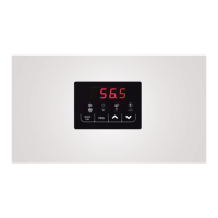
Describes the information shown on the controller's display.
Explains the meaning of different LED indicators on the unit.
Adjusts setpoints based on outdoor air temperature for efficiency.
Manages the operation modes of the circulation pump.
Describes the default circulator operation linked to the thermoregulator.
Details periodic activation of the circulator for thermoregulation.
Explains circulator operation when auxiliary electric heaters are active.
Circulator runs continuously in this mode, independent of compressor status.
Regulates circulator speed based on water inlet/outlet temperature difference.
Procedure for purging air from the system using the circulator.
Manages the activation and logic of compressors.
Describes the initial phase of compressor startup and valve operation.
Details how ON/OFF compressors are activated based on modulating compressor capacity.
Explains the conditions under which ON/OFF compressors stop.
Manages inverter compressor operation based on temperature and setpoints in cooling.
Manages inverter compressor operation based on temperature and setpoints in heating.
Specifies minimum waiting times for compressor on/off actions.
Describes actions and parameters for emergency situations.
Conditions for deactivating compressors due to low outdoor temperature.
Normal operation mode where auxiliary heaters assist the heat pump.
Controls the fan speed based on system pressure and operation mode.
General principles for controlling fan speed.
Specific fan speed control parameters for cooling operation.
Specific fan speed control parameters for heating operation.
Manages the defrost cycle to prevent frost formation.
Procedure to manually initiate a defrost cycle.
Operation of the compressor crankcase heater for protection.
Operation of electric heaters for antifreeze protection.
Controls unit operation remotely via a digital input.
Configures a digital output for defrosting cycle warnings.
Configures a digital output for plant season mode signaling.
Configures a digital output for general alarm signalization.
Configures a digital output for heat pump lockout warnings.
Enables and configures domestic hot water production features.
Stores sensor readings when switching between water and DHW modes.
Activates sanitary mode via a digital input signal.
Utilizes the DHW tank for plant heating under specific conditions.
Allows remote switching between summer and winter operating modes.
Enables the use of a plant temperature sensor for regulation.
Configuration and utilization of auxiliary electric heaters.
Details the plant circuit auxiliary electric heater's operation and parameters.
Activation of plant auxiliary heater during defrost cycle.
Details the auxiliary electric heater for DHW production.
Using a single heater for both plant and DHW systems.
Defines the priority order for auxiliary electric heater activation.
Manages circulator operation when auxiliary electric heaters are active.
Configuration and utilization of an external boiler.
Describes combined and substitution operations with auxiliary elements.
Auxiliary elements activate if the heat pump enters an error state.
Operation where heat pump works with auxiliary heaters in a specific temperature range.
Operation with auxiliary heaters and boiler in a different temperature range.
Auxiliary elements take over when the compressor is inhibited due to low temperature.
Details operation areas for auxiliary heaters and boilers without a plant sensor.
Adjusts setpoints for boilers and heaters to supplement heat pump output.
Enables a second setpoint for plant side operation.
Configuration options for double setpoint activation modes.
Defines the values for the first and second setpoints.
Describes the sequence for switching between setpoints.
Manages a secondary circulator based on thermostat input.
Lists allowed configurations for setpoint parameters.
Lists allowed configurations for general system parameters.
Lists allowed configurations for alarm parameters.
Lists allowed configurations for various setting parameters.
Lists allowed configurations for condensation control parameters.
Lists allowed configurations for circulator pump parameters.
Lists allowed configurations for defrosting parameters.
Lists allowed configurations for compressor parameters.
Lists allowed configurations for the optional GI module.
Alarm code for remote ON/OFF control status.
Alarm for high pressure detected in the system.
Alarm for low pressure detected in the system.
Thermal overload protection for the first ON/OFF compressor.
Alarm indicating a fault with the fan motor driver.
Alarm triggered by low outlet water temperature.
Alarm indicating low water flow or air in the system.
Alarm for failure to reach expected compressor speed.
Thermal overload protection for the second ON/OFF compressor.
Alarm for excessively high water temperature on the outlet side.
Thermal protection alarm for the AC circulator driver.
High pressure alarm detected by the built-in switch.
Alarms for short/open circuits or out-of-range sensor readings.
Alarm for loss of communication with the compressor driver.
Describes system behavior after a power supply interruption.
Comprehensive list of alarm codes and their descriptions.
Details conditions that cause a heat pump lockout and recovery.