i-MAX Industrial inverter air/water heat pump with axial fans
8
Level 1 (M) = it’s visible if you enter the maintainer or manufacturer password
Level 2 (C) = it’s visible if you enter the manufacturer password
Level 3 (A) = it’s visible only via Modbus
5.2 MENU CONTENTS
The main functions of the menus are listed below, especially when there are some unambiguous functions. The main menu
manages the following parameters:
Not accessible if the Hi-T control panel is connected
Only in case of active alarms
Number of operating hours
Only in the USB flash drive is present with its files
You have to enter in the password menu for inserting its password in order to enable an access with a greater privilege. Once you
exit completely from the menus, you lose the password concession and need to re-enter it again for getting access.
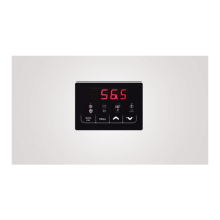
5.2.1 Setpoint menu
You can display and change the different setpoints.
First setpoint in the summer
First setpoint in the winter
Second setpoint in the summer
Second setpoint in the winter
5.2.2 Password menu
Enter the password for the desired access level. The controller will automatically open the desired access level and then they will
appear on this level the test items which can be enabled from this level.
5.2.3 Sensors menu
The value of the various probes is displayed. The number of visible sensor depends on the presence of the I/O expansion modules.
Particular cases:
• Err = Sensor is faulty
• --- = Sensor not used (no function is associated to such sensor)
By entering the maintainer password in the menu of analog inputs "tP", at the level 1 of the menu structure diagram of the on-
board control panel, you can read the values of the current sensors:
Compressor intake temperature
Compressor discharge temperature
Plant water temperature remote sensor (if present)
Domestic hot water temperature (if present)
(*) If the “Gi” optional module is installed.
5.2.4 Alarms menu
This menu appears only in case of alarms warning. You can check all active alarms. For multi-circuit units (the ALCx label allows to
get access to the alarms of the circuit number x) the alarms are divided by circuit.
5.2.5 Digital inputs menu
You can check the status of the digital inputs as below:
0 = inactive input
1 = active input