i-MAX Industrial inverter air/water heat pump with axial fans
10
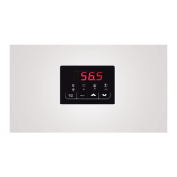
5.2.10 LED STATUS DESCRIPTION
Compressor LED
• ON if the compressor is running
• OFF if the compressor is off
•
FLASHING if timings are in progress waiting for compressor’s start up.
Sanitary water LED
• ON if sanitary mode is fulfilled active
• OFF if the sanitary mode is not active
• FLASHING if the sanitary production is in progress (sanitary valve is active)
Defrosting LED
• ON in defrost operating mode
• OFF if defrosting mode is disabled or completed
• FLASHING if defrosting cycle interval’s time counting is in progress.
Antifreeze electric heater LED
• The LED is ON if the antifreeze electric heater is active.
Water pump LED
• The LED is ON if the water pump is running.
Alarm LED
• The LED is ON if an alarm is activated.
Heat LED
• The LED is ON if the unit is in the heating mode operation.
Cool LED
• LED is ON if the unit is in the cooling mode operation.
6 I/O PORTS OF THE SYSTEM
The configurable I/O ports are as follows:
Parameter
Value = Function Terminals Notes
Remote on-off digital input
Voltage free contact input
*H81 0
21= Defrosting cycle signalization
24= Alarm signalization
31=Plant season signalization
DO3(phase)
DO3N(neutral)
Under voltage output 230Vac, 50Hz, 2A (AC1).
(*) For the sizes of 0466, 0475 and 0485
Wherever the GI optional plant management kit is present, you have a third controller located inside the electrical board acting as
an expansion module of the I/O ports. By mean of this controller, it is therefore possible to increase the number of logic functions
that can be managed by the main controller; in particular, the following I/O ports can be activated by the previous controller.
Parameter
Value = Function Terminals Notes
H57 0
3=Selected mode
19=Thermostat
26=Double set point
ID3E Voltage free contact input
NTC-10kΏ at 25°C β 3435
41=Plant circuit water remote sensor
H86
0 21=Defrost cycle warning
Under voltage output 230Vac, 50Hz, 2A
(AC1).
H87
0 31=Plant season warning
H88
0
24=Alarm warning
47=Lockout warning
H89
0 6= Sanitary valve
H90
0
26= Double set-point valve
43= Secondary circulator
7 OPERATION’S LOGICS
The following operation logics are enabled by the master controller CB (MASTER), situated on the front panel of the unit.