MAXEONSOLARTECHNOLOGIES,LTD.
SafetyandInstallationInstructions‐Document544753Rev.A
©2022MaxeonSolarTechnologies,Ltd.Allrightsreserved.Specificationsincludedintheseinstructionsaresubjecttochangewithoutnotice.Page|3
irradianceperIEC60904‐3orirradiationof(airmass)AM1.5global(G)spectrum.
Eachmodulecontainsthreebypassdiodes.Themaximumseriesfuseratingis
15A(X‐Series),forMAX3andMA X6modulesitis20A
Undernormalconditions,aphotovoltaicmodulemayexperienceconditionsthat
producemorecurrentand/or
voltagethanreportedatStandardTestConditions.
Accordingly,thevaluesofISCandVOCmarkedonULListedmodulesshould
alwaysbemultipliedbyafactorof1.25whendeterminingcomponentvoltage
ratings,conductorcapacities,fusesizesandsizeofcontrolsconnectedtothe
moduleoutput.RefertoSection690‐
8oftheNECforanadditional1.25Safety
factorwhichmaybeapplicable.
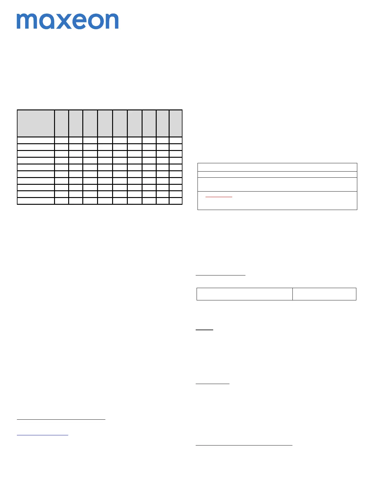
Table1:ElectricalCharacteristics
1
Module
Rated
Power
(W)
+5/‐0%
Voltage
atRated
Power
Vmpp
(V)
Current
atRated
Power,
Impp(A)
Open
Circuit
Voltage
Voc(V)
+/‐3%
Short
Circuit
Current,
Isc(A)
+/‐3%
Current
Temp.
Coeff.
%/°C
Voltage
Temp.
Coeff.
%/°C
Power
Temp.
Coeff.
%/°C
System
Safety
Class
SPR‐MAX3‐420‐BLK‐R 420 35.5 11.82 40.7 12.65 0.058 ‐0.236 ‐0.27 II
SPR‐MAX3‐415‐BLK‐R 415 35.3 11.75 40.7 12.64 0.058 ‐
0.236 ‐0.27 II
SPR‐MAX3‐410‐BLK‐R 410 35.1 11.68 40.7 12.63 0.058 ‐0.236 ‐0.27 II
SPR‐MAX3‐430‐R 430 35.1 12.25 40.7 13.15 0.058 ‐0.236 ‐0.27 II
SPR‐MAX3‐425‐R 425 34.9 12.18 40.7 13.13 0.058 ‐0.236 ‐0.27 II
SPR‐MAX3‐415‐R 415 34.5 12.03 40.6 13.10 0.058 ‐0.236 ‐0.27 II
SPR‐MAX6‐480‐COM 480 44.2 10.87 52.6 11.58 0.060 ‐0.239 ‐0.30 II
SPR‐MAX6‐475‐COM 475 43.9 10.82 52.6 11.57 0.060 ‐0.239 ‐0.30 II
SPR‐MAX6‐460‐COM 460 43.2 10.64 52.5 11.54 0.060 ‐0.239 ‐0.30 II
SPR‐MAX6‐450‐COM 450 42.8 10.52 52.4 11.51 0.060 ‐0.239 ‐0.30 II
4.0 ElectricalConnectionsandSystemMonitoring
Modulesmaybeconnectedinseriesand/orparalleltoachievethedesired
electricaloutputaslongasoptimumdesignparametersareachieved.Pleaseuse
onlythesametypeofmodulesinacombinedsourcecircuit.Donotmixthe
moduleswithdifferentnameplateswithoutauthorizationbyMaxeon.
Evenifallowedby
localregulation,PlugandSocketconnectorsmatedtogetherin
aPVsystemmustbeofthesametype(model,rating)fromthesame
manufactureri.e.aplugconnectorfromonemanufacturerandasocket
connectorfromanothermanufacturer,orviceversa,shallnotbeusedtomakea
connection.Currently
approvedcompatibleconnectorsare:Tyco,ModelPV4‐
S1M4/F4orStaubli,ModelPV‐KST4andKBT4/6II‐UR.
Maxeonrecommendsaconservativemi nimumbendingradius(R)5xcable
diametermustbemaintainedandmustnotbebentonthedirectexitofthe
connectororjunctionbox.Avoidexposureofelectricalconnectionsto
direct
sunlightanddonotplacetheconnectorinalocationwherewatercouldeasily
accumulate.Installersmustrefertoconnectormanufacturer’sinstructionfor
furtherinstallationandconnectionrequirements.
Connectorsarefactoryassembledwithintentionalgapsbetweenthe cabl enut
andthebodyoftheconnector.Donotretightenmodule
connectornutsasthis
mayleadtostresscrackingoftheconnectorassemblyandwillvoidthewarranty.
4.1EquipmentGrounding
Toreducethepossibilityofelectricalshock,groundtheframeofthemoduleor
arrayperNECbeforewiringthecircuit.Inordertoinstallinaccordancewiththeir
ULListing,Maxeonmodulesmustbegroundedusinggroundinghardwarethat
meetsrequirementsforgroundingsystemsinUL61730andUL61215
on
anodizedaluminumframes.Maxeonrecommendstorefertotheapplicable
regionalandlocalcodesandrequirementsongroundingPVarraysandmounting
framesinconjunctionwithyourrackingsupplier.
1
Formodelsnotshownhere,pleasecontactMaxeontechnicalsupportorvisit
www.sunpower.maxeon.com.ElectricalparametersaremeasuredatStandardTest
Conditions(STC).Theseriesfusemusthaveaninterruptingratingthatisequaltoorgreater
thanthemaximumfaultcurrentthatthefuseisrequiredtointerrupt,includingcontributions
fromallconnectedsourcesofenergy.
RefertoNECArticle100,PartIIastowhattypeofseriesfuseis
acceptableformodulesrated
athigherthan600Vdcsystemvoltage.
Inaddition,toavoidcorrosionduetotheuseofdissimilarmetalsMaxeon
recommendsstainlesssteelbetweencopperandaluminum.
4.2SystemGrounding
ReviewTable2belowforthepropergrounding techniquesfortheinstallationof
yourparticularMaxeonmodules.
4.3SeriesConnection
Themodulesmaybewiredinseriestoproducethedesiredvoltageoutput.Do
notexceedthemaximumsystemvoltageshowninmoduledatasheetsand
productlabel.
4.4ParallelConnection
Themodulesmaybecombinedinparalleltoproducethedesiredcurrentoutput.
Eachseriesstringormodulemayberequiredtobefusedpriortocombiningwith
otherstringsiftheresultingmaximumfusesizeallowed(numberofmodules
whichcanbeconnectedinparallelandprotectedbyonefuse)
exceedsthefuse
ratingasshowninthemoduledatasheetandproductlabel.Pleaserefertothe
NECArticle690foradditionalfusingrequirements.
Table2:ModuleGroundingKey
ModuleModelGroundingKey
MaxeonP‐Seriesmoduleshavenogroundingrestrictions:
AllmodelnumbersstartingwithSPR‐MAX3‐xxx‐R,SPR‐MAX3‐xxx‐BLK‐
R,SPR‐MAX6‐xxx‐COM
IMPORTANT!P‐Seriescanbegroundedwitheitherpolarity.Failureto
complywiththisrequirementwillreducesystemperformanceand
invalidateMaxeon’sLimitedPowerWarrantyforPVModules.
5.0 ModuleMounting
TheMaxeonLimitedWarrantyforPVModulesiscontingentuponmodulesbeing
mountedinaccordancewiththerequirementsdescribedinthissection.
5.1SiteConsiderations
Maxeonmodulesshouldonlybemountedinlocationsthatmeetthefollowing
requirements:
OperatingTemperature:AllMaxeonmodulesmustonlybemountedin
environmentsthatensuretheywilloperatewithinthefollowingtemperatures:
OperatingTemperaturerange(ambient)
‐40°Cto+85°C
‐40°Fto+185°F
Adequateventilationshouldbeprovidedbehindthemodules,especiallyinhot
environments.
Shading:Modulesshouldbeinstalledsothatpermanen tshadingofcellsis
avoidedandpartialshadingthatmayoccurduringcertaintimesofthedayor
yearisminimized.
Permanentshadingisdefinedasshadethatiscastoverthe
sameposition(ofconstantarea)ofthesolarmodulethroughout thegeneration
hoursoftheday.
Shadingmayinduceincertaincasesstrongenergyproductionreduction,evenin
caseofsmallshadingandshouldbeavoidasmuchaspossible,
especiallyatmid‐
daywhentheproductionismaximum.
DesignStrength:Maxeonmodulesaredesignedtomeetapositive(downward)
and/ornegative(upward)withstandingtestpressureload,asperIEC61215,
whenmountedaspertheguidelinesinSection5.2andconfigurationsin
Appendix.Testloadsareforinformationpurposesonly;designloadsshouldbe
consideredfortheprojectdesign.
Whenmountingmodulesinsnowproneorhighwindenvironments,specialcare
shouldbetakentomountthemodulesinamannerthatprovidessufficient
designstrengthwhilemeetinglocalcoderequirements.
AdditionalauthorizedOperatingEnvironments:
Modules can be mounted in the following aggressive environment according to
thetestlimitsmentionedbelow
Saltmistcorrosiontesting:IEC61701Severity6
 Loading...