MAXEONSOLARTECHNOLOGIES,LTD.
SafetyandInstallationInstructions‐Document544753Rev.A
©2022MaxeonSolarTechnologies,Ltd.Allrightsreserved.Specificationsincludedintheseinstructionsaresubjecttochangewithoutnotice.Page|4
AmmoniaCorrosionResistance:IEC62716Concentration:6,667ppm
Modulesaredesignedforamaximumaltitudeof2000m.
ExcludedOperatingEnvironments
CertainoperatingenvironmentsarenotrecommendedforMaxeonmodules,and
areexcludedfromtheMaxeonLimitedWarranty.
NoMaxeonmoduleshouldbe
mountedatasitewhereitmaybesubjecttodirectcontactwithsaltwater,or
otheraggressiveenvironment.
Modulesshouldnotbeinstallednearflammableliquids,gases,orlocationswith
hazardousmaterials;ormovingvehiclesofanytype.
5.2MountingConfigurations
Modulesintegratedintoormountedoveraroofingsystemmustbemounted
overafire‐resistantroofcoveringratedfortheapplication.Modulesmaybe
mountedatanyangle,fromhorizontaltovertical.Toreducesoiling,modules
shouldbemountedataminimumof5degrees.
Commercialmodules(128cells)
frameshavepermanentlyattachedstackingpins
locatedina20mmzoneonthelongsideframeat388‐408mmfromthecorner.
Mountingsystemhardwareusedwithcommercialmodulesmustaccount forthe
presenceofthesestackingpins(seeAppendix).
Specificinformationonmoduledimensionsandthelocationof
mountingand
groundingholesisprovidedinAppendix.Thesysteminstallerisresponsiblefor
thedeterminationoflocation‐specificloadrequirements.
Inordertopreventwaterfromenteringthejunctionbox,whichcouldpresenta
safetyhazard,modulesshouldbeorientedwiththejunctionboxinthe
uppermostpositionand
notbemountedsuchthatthecellfacesdownward(e.g.
onatrackingstructurethatpositionsthemoduleswiththejunctionboxfacing
skywardduringsleepmode).
ItshouldbenotedthatwatertightnessisnotensuredbyMaxeon,therefore,if
watermanagementisrequired,themountingsystemshouldbedesigned
accordingly.
Clearancebetweenthemoduleframesandstructureorgroundisrequiredto
preventwiringdamageandallowsairtocirculatebehindthemodule.Forall
modulesaminimumof1.5″ofclearancebetweenthemoduleframesandthe
structure(orgrade)isrequired.Therequiredminimumclearancebetween
installedmodules
is1/4″.
Wheninstalledonaroof,themoduleshallbemountedaccordingtothelocaland
regionalbuildingandfiresafetyregulations.Incasethemoduleisinstalledina
roofintegratedPV‐System(BIPV),itshallbemountedoverawatertightandfire‐
resistantunderlaymentratedforsuch
application.
Modulesmountingsystemsshouldonlybeinstalledonbuildingsthathavebeen
formallyconsideredforstructuralintegrity,andconfirmedtobecapableof
handlingtheadditionalweightedloadoftheModulesandmountingsystems,by
acertifiedbuildingspecialistorengineer.
Mountingsystemsuppliershallmanagethegalvaniccorrosion
whichcanoccur
betweenthealuminumframeoftheModulesandmountingsystemorgrounding
hardwareifsuchdevicesiscomprisedofdissimilarmetals.
Themoduleisonlycertifiedforusewhenitsfactoryframeisfullyintact.Donot
removeoralterthemoduleframe.Creatingadditionalmountingholesor
removingthestackingpinsmaydamagethemoduleandreducethestrengthof
theframe,thereforearenotallowed.UsingmountingClampsorclipswith
additionalgroundingboltsorgroundingmetalsheetscouldbeincompliancewith
thisSafetyandInstallationInstructionsmanualsubjecttoconditionsofSection
4.1
Modules
maybemountedusingthefollowingmethodsonly:
1) FrameHoles:Securethemoduletothestructureusingthefactory
mountingholes.Four1/4″stainlesssteelbolts,withnuts,washers,andlock
washersarerecommendedpermodule;tightenedtoamin.torqueof10in‐
lb.Thismethodhasbeencertified
byathird‐partyorganizationaccordingto
UL1703.Forframeholemounting,modulesmustbesecuredusingthe
holesshowninAppendix.
2) Clamps: Mountthemodulewiththeoppositeclampsonthelongerand/or
shortersidesofthemodule.Theclips
allowedlocationshouldbeaccording
toAppendix.Installers
shouldensure
theclampsareofsufficientstrength
toallowforthemaximumdesign
pressureofthemodule.Clampsare
notprovidedbyMaxeon.Clampsmust
applyforcecollinearwiththe‘wall’of
themoduleframeandnotonlytothe
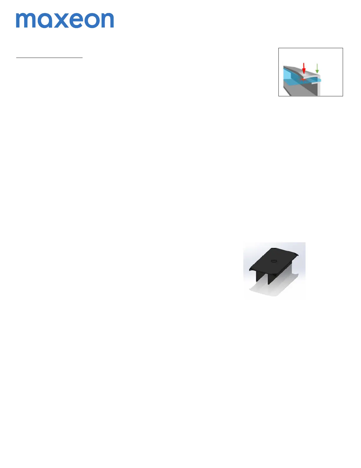
topflange.Clampsshallnotapply
excessiveforceto
thetopframe,warpthetopflangeorcontacttheglass‐
thesepracticesvoidthemodulewarrantyandriskglassbreakage.Figure1a
illustrateslocationsfortopframeclampforce.Whenclampingtothe
moduleframe,torqueshouldneverexceed132in‐lbs(15Nm)toreduce
chancesofframedeformation
and/orglassbreakage.Iftheclamp
manufacturerrecommendsa specifictorquevaluewhichislowerthan132
in‐lbs(15Nm),theinstallershouldusetheclampmanufacturer’storque
value.Iftheclampmanufacturerrecommendsaspeci f ictorquevalue
whichishigherthan132in‐lbs(15Nm),theinstaller
shouldcontactthe
clampmanufacturerforacceptanceofthe132in‐lbs(15Nm)maximum
torquevalueortofindalternativeclamps.Acalibratedtorquewrenchmust
beused.Mountingsystemsshouldbeevaluatedforcompatibilitybefore
installing,especiallywhenthesystemisnotusingClampsorclip.
Maxeondoesnot
recommendnorendorsetheapplicationonthemodules
ofclampswhich,aspartoftheirgroundingorearthingfunction,haveteeth
orclawfeatureswhichmay,individuallyorcumulatively,causethemodule
breakagedueto(andwithoutlimitation):
i.thegroundingfeaturestouchingthefrontglasswhichisincorporatedinto
themoduleduetothepositionofsuchgroundingfeature,
ii.theshape,thepositionorthenumberofthegroundingfeatures
deformingthemoduletopframe,or
iii.theclampbeingover‐torquedduringtheinstallation.
Maxeonshallnotbeliableforanydamagesorlosseswhatsoeverarising
fromtheusebytheInstallerofanysuchclampsonitsmodules,and
disclaimsallwarranties,expressorimplied,applicabletothosemodules
shouldtheybedamagedinanywaybysuchclamps.Therefore,theuseof
theabovementionedclampsbytheInstallerisattheInstaller'ssolerisks.
5.2ModuleHandling
Donotplacemodulesfaceforwardindirectcontactwithabrasivesurfaceslike
roofs,driveways,woodenpallets,railings,stuccowalls,etc…
Themodulefrontsurfaceglassissensitivetooilsandabrasivesurfaces,which
mayleadtoscratchesandirregularsoiling.
Duringstorage,modulesneedtobeprotectedfromrainor
anykindsofliquids.
Requiredstoragetemperatureisbetween10°Cto40°Cinadryenvironment
(humiditybetween30to80%).Donotstoremodulesoutdoortoavoidmoisture
andwetconditions.
Modulesthatfeatureantireflectivecoatedglassarepronetovisiblefingerprint
marksiftouchedonthefront
glasssurface.Maxeonrecommendshanding
moduleswithanti‐reflectiveglasswithgloves(noleathergloves)orlimiting
touchingofthefrontsurface.Anyfingerprintmarksresultingfrominstallation
willnaturallydisappearovertimeorcanbereducedbyfollowingthewashing
guidelinesinSection6.0below.Anymodulecoverage(colored
plastictarpsor
similar)duringinstallationcanleadtopermanentfrontglassdiscolorationandis
notrecommended.Theuseofvacuumliftingpadscancausepermanentmarks
Force must not deform
top frame flange or
glass may break
Force
has to
be
applied
in line
with
frame
wall
Figure 1a: Clamp Force Locations
 Loading...