Maxim Integrated Page 4 of 15
1 Architecture
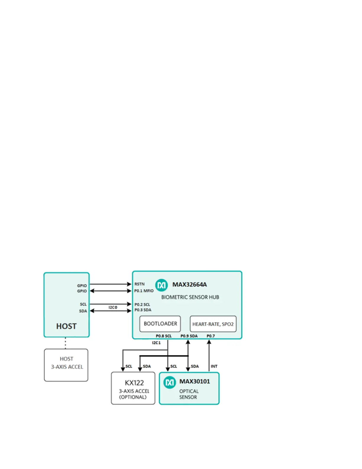
A typical health-sensing design includes a host microcontroller that communicates with the
MAX32664A through the I
2
C bus. Two GPIO pins are needed to control the reset and the startup
in Application or Bootloader mode through the RSTN and multifunction input/output (MFIO) pins.
An MFIO pin is also used in Application mode to interrupt the host for I
2
C communication. The
MAX32664A interfaces with the MAX30101 optical sensor through a second I
2
C bus.
To enter Bootloader mode:
• Set the RSTN pin to low for 10ms.
• While RSTN is low, set the MFIO pin to low. (The MFIO pin should be set to low at least
1ms before the RSTN pin is set to high.)
• After the 10ms has elapsed, set the RSTN pin to high.
• After an additional 50ms has elapsed, the MAX32664 is in Bootloader mode.
To enter Application mode:
• Set the RSTN pin to low for 10ms.
• While RSTN is low, set the MFIO pin to high.
• After the 10ms has elapsed, set the RSTN pin to high. (The MFIO pin should be set to
high at least 1ms before the RSTN pin is set to high.)
• After an additional 50ms has elapsed, the MAX32664 is in Application mode and the
application performs its initialization of the application software.
• After approximately 1 second from when the RSTN pin was set to high, the application
completes the initialization and the device is ready to accept I
2
C commands.
Figure 1 shows the top-level architecture.
Figure 1. Architecture diagram for health-sensing applications.