Maxim Integrated Page 9 of 15
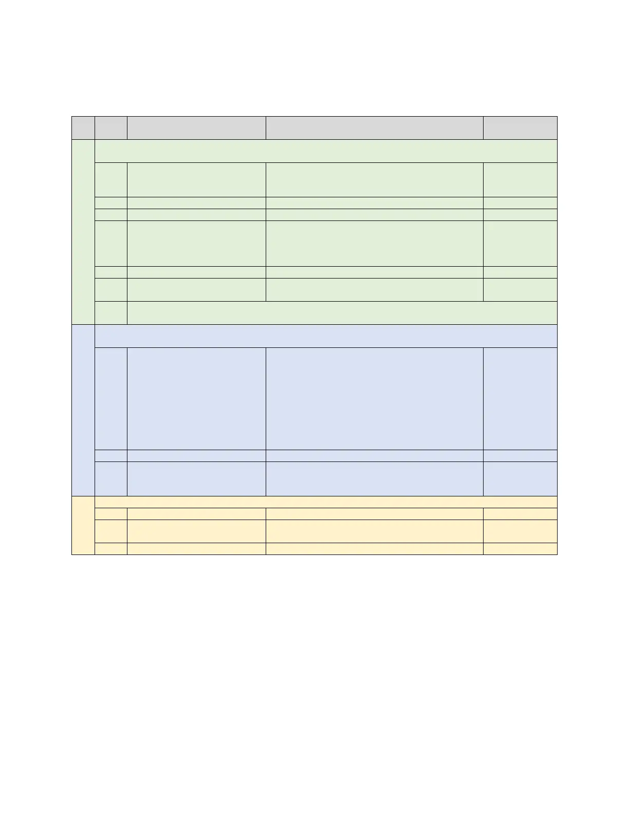
Table 4 shows the list of commands to start the SpO
2
calibration.
Table 4. Host Commands—SpO
2
Calibration
#
COMMAND DESCRIPTION
START ALGORITHM
Host initializes the MAX32664A in calibration mode and starts the algorithm using following
commands:
Set the output mode to sensor + algorithm
data (0x03) (streamed data will include PPG,
accelerometer, and algorithm data).
Set the sensor hub interrupt threshold.
AA 44 04* 01 00 (if sensor
hub accelerometer is used)
AA 44 04* 01 01 (if Host
Enable the accelerometer with the sensor
hub or host-side accelerometer.*
(Do not use this command if there is no
Enable the AFE (e.g., the MAX30101).
2
2
algorithm. The format of
the samples is shown in Table 5.
Wait for 100ms before sending the next command. Any command to change sensor
registers should appear AFTER enabling the algorithm or they will be overwritten.
Host reads the samples upon receiving the MFIO interrupt from the MAX32664A. For SpO
2
calibration, continue as needed to capture the R value. See Table 5.
Read the sensor hub status byte:
Bit 0: Sensor comm error
Bits 1 and 2: Reserved
Bit 3: FIFO filled to threshold (DataRdyInt)
Bit 4: Output FIFO overflow (FifoOutOvrInt)
Bit 5: Input FIFO overflow (FifoInOverInt)
Bit 6: Sensor hub busy (DevBusy)
Bit 7: Reserved
If DataRdyInt is set, proceed to the next step.
Get the number of samples (nn) in the FIFO.
Read the data stored in the FIFO; nn
samples (30 bytes each) will be read. The
format of the samples is shown in Table 5.
data_for_
STOP
Disable the AFE (e.g., the MAX30101).*
Disable the accelerometer.* (Do not use this
command if there is no accelerometer.)
*Provided indexes are example for sensors such as the MAX30101 AFE or KX122 accelerometer