30
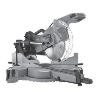
model no. 055-6767-0 | contact us 1-888-670-6682
ADJUSTMENTS
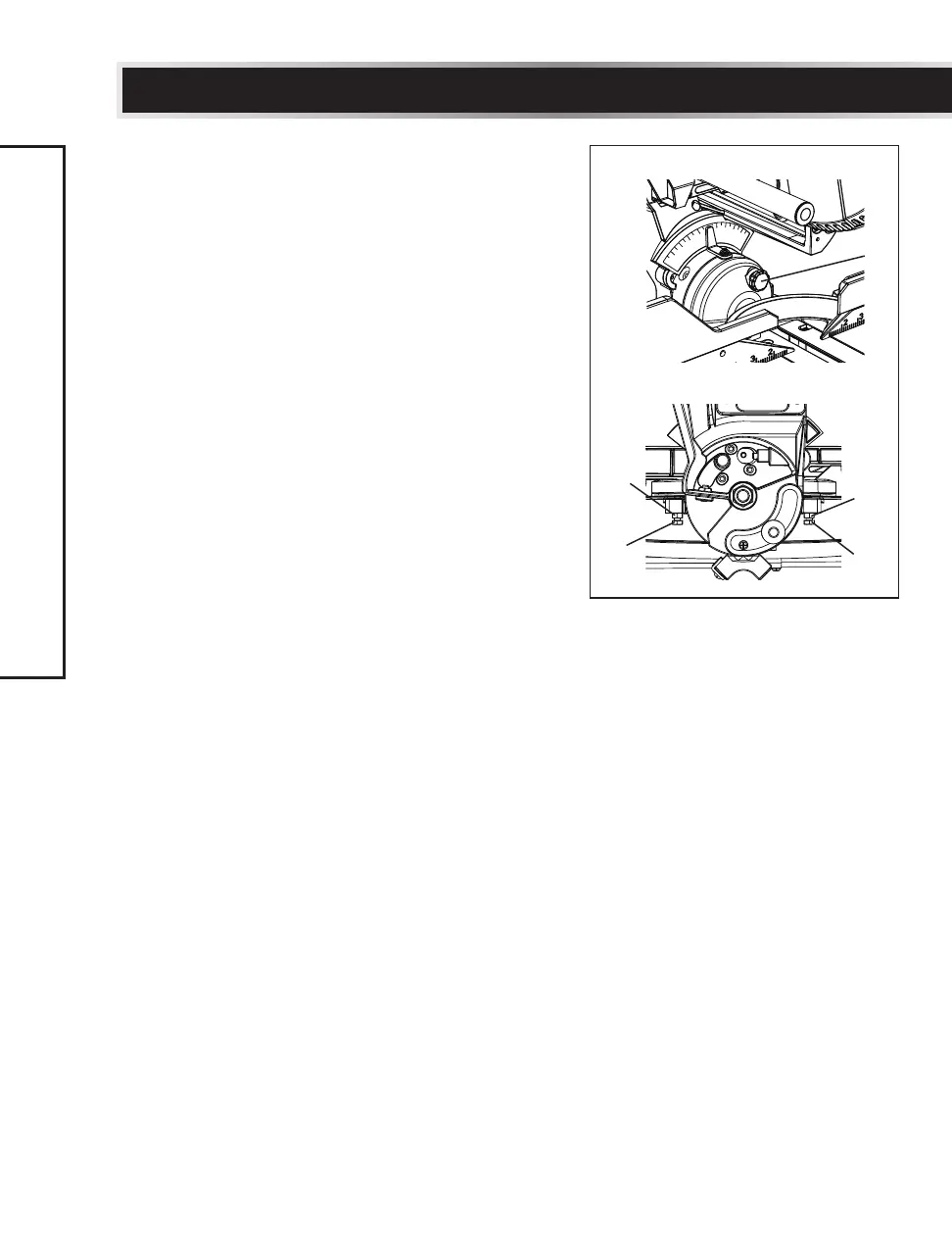
45° Left bevel positive stop adjustment
(Fig. 17, 19)
• Fully extend the sliding fence completely
to the left, and then pull the bevel detent
pin (6) towards the front of the machine.
NOTE: When retracting the bevel detent
pin, it may be necessary to shift the mitre
saw upper arm assembly to the left/right to
release the holding pressure.
• Loosen the bevel locking handle (1) and
tilt the cutting arm completely to the left.
(Fig. 17)
• Using a combination square, check to see if
the blade is 45° to the table.
• To adjust, tilt the cutting arm to 0°, loosen
the locknut (7), and turn the bolt (8) in or
out to increase or decrease the angle.
• Tilt the cutting arm back to the left, and
recheck alignment.
• Repeat steps until the blade is 45° to
the table. Once alignment is achieved,
tighten the locknut (7) to secure the
positive stop bolt.
45° Right bevel positive stop adjustment
(Fig. 17, 19)
• Set the mitre angle to 0°. Fully extend the
sliding fence completely to the right, and
then pull the bevel detent pin (6) towards
the front of the machine.
NOTE: When retracting the bevel detent
pin, it may be necessary to shift the mitre
saw upper arm assembly to the left/right to
release the holding pressure.
• Loosen the bevel locking handle (1) and
tilt the cutting arm completely to the right.
(Fig. 17)
• Using a combination square, check to see if
the blade is 45° to the table.
• To adjust, tilt the cutting arm to 0°, loosen
the locknut (9), and turn the bolt (10) in or
out accordingly.
• Tilt the cutting arm back to the right, and
recheck alignment.
• Repeat steps until the blade is 45° to
the table. Once alignment is achieved,
tighten the locknut (9) to secure the
positive stop bolt.
Fig. 19
6
8
7
10
9