22
model no. 055-6767-0 | contact us 1-888-670-6682
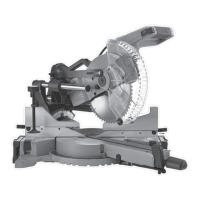
Fig. 3
ASSEMBLY
INSTALLING THE BEVEL LOCKING
HANDLE (Fig. 3)
• Insert the bevel locking handle (1) onto the
shaft (2) at an approximately angle 30°
below the level as shown in Fig. 3.
• Thread the hex screw (3) through the
washer (4) into the bevel locking handle (1).
• Tighten the screw (3) with the 5 mm
hex wrench.
INSTALLING THE MITRE HANDLE (Fig. 3)
• Insert the mitre handle (5) into the hole in
front of the mitre saw and align the hole (6)
on the mitre handle (5) with the hole (7) in
the front of the table.
• Thread the screw (8) through the hole (7)
in the table into the hole (6) on the mitre
handle (5).
• Tighten the screw (8) with a screwdriver.
INSTALLING THE HOLD-DOWN CLAMP
ASSEMBLY (Fig. 4, 5)
• Place the hold-down clamp assembly (1)
facing toward the back of the mitre saw as
shown in Fig. 4.
• The groove on the clamp rod should be
fully inserted into the mounting hole (2) of
the base without being visible.
• Rotate the hold-down clamp assembly (1)
toward the front of the mitre saw.
• Loosen the knob (3) to adjust the clamp up
or down to firmly clamp the workpiece.
• The hold-down clamp assembly (1) can be
inserted in one of the mounting holes (2)
located behind the fence.
Fig. 4
Fig. 5
2
1
5
6
7
2
3
4
8
WARNING!
• To avoid interference, the bevel locking handle shall be installed before
the mitre handle.
2
1
3