9
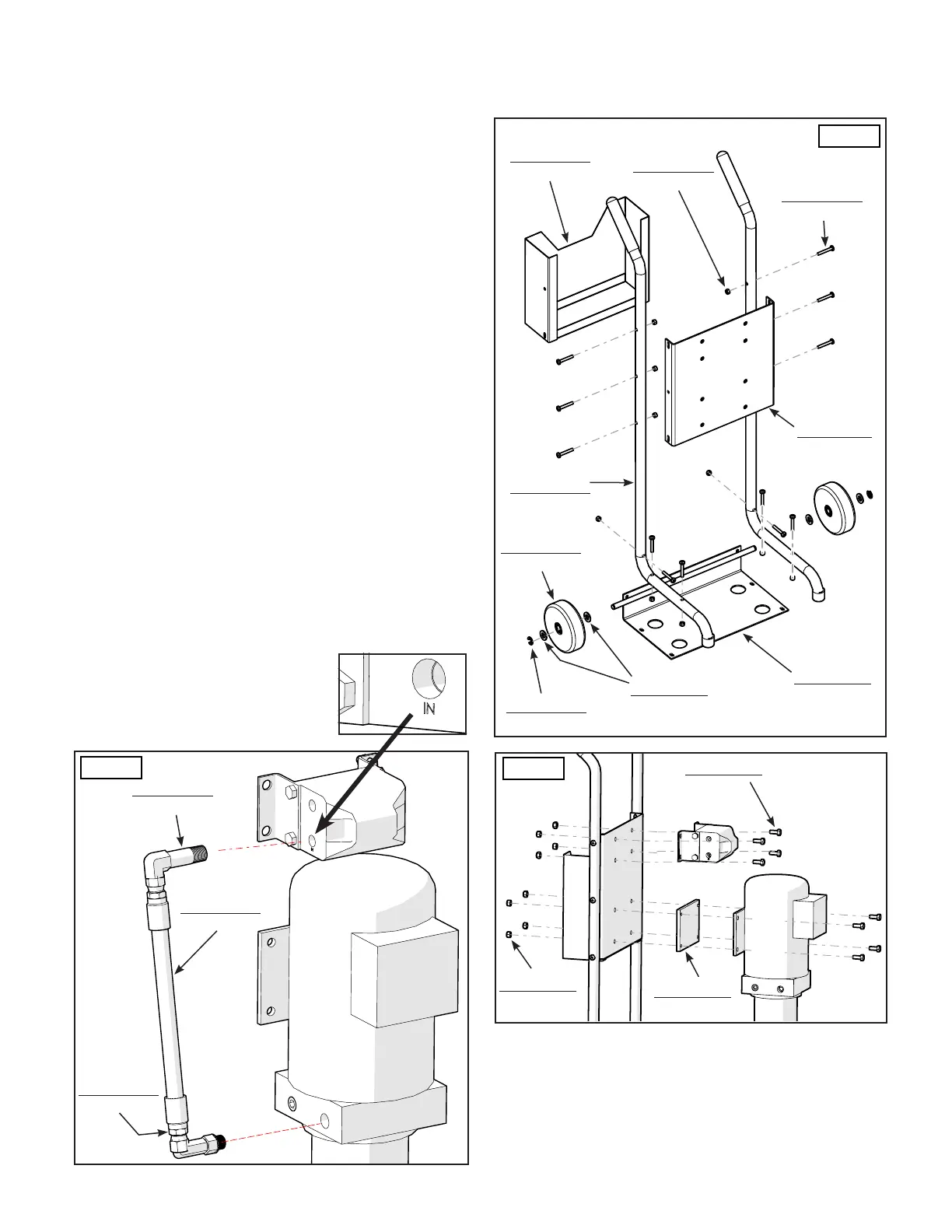
1. Assemble the Cart as shown. (See Figure 7)
2. Attach the Power Unit and Hydraulic Flow Divider to the
Power Unit Cart using 8 Hex Head Bolts (P/N 5530304) and
Nylon Nuts (P/N 5535001). (See gure 8)
NOTE:
Install the Hydraulic Flow Divider so that when facing it
from the front, the OUT Ports are on the top, and the
lower ports are IN.
3. Remove the Shipping Plug from the Lower Left Port
stamped "IN" on the Flow Divider. Install the Long 90°
Elbow Fitting (P/N 5550170). When tightening the Fitting,
hand tighten rst and then using a wrench turn approx.
3 turns past tight. (See gure 9)
NOTE:
Use the include Liquid Thread Sealant to seal the
connections made to the Hydraulic Flow Divider.
Use Liquid Thread Sealant on NPT threads only.
4. Remove the plastic plug from the Hydraulic Pressure
Port (usually labeled as P1 / P2) on the Power Unit and
attach the Long 90°Elbow Fitting (P/N 5550074).
5 Attach the Short Power Unit Hose (P/N 5570242) as
shown. DO NOT use Teon Tape on the JIC Fittings.
(See Figure 9)
* SEE FOLLOWING PAGE *
STEP 4
MOUNTING THE HYDRAULIC POWER UNIT
P/N 5550170
1
P/N 5550074
1
P/N 5570242
1
P/N 5530378
12
P/N 5601474
1
P/N 5755171
2
P/N 5535357
12
P/N 5737162
1
P/N 5540113
2
P/N 5545141
4
P/N 5215970
2
P/N 5601535
1
P/N 5530304
8
P/N 5535001
8
Fig. 7
Fig. 8
Fig. 9
P/N 5715003
1
 Loading...